
Page 138 - Engineering drawing from first principles using AutoCAD
P. 138
Three-dimensional projection exercises 131
o
(J)
RH--+-I~
A
B
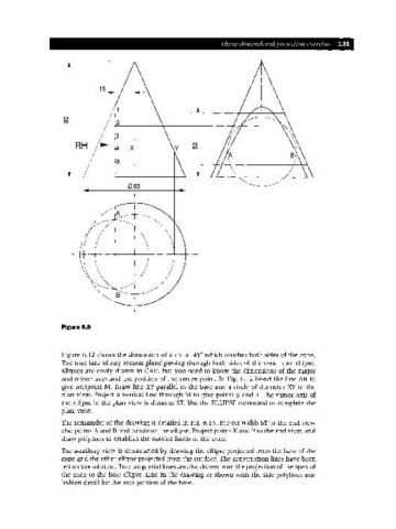
Figure 6.9
Figure 6.12 shows the dimension of a cut at 45° which touches both sides of the cone.
The true face of any section plane passing through both sides of the cone is an ellipse.
Ellipses are easily drawn in CAD, but you need to know the dimensions of the major
and minor axes and the position of the centre point. In Fig. 6.12 bisect the line AB to
give midpoint M. Draw line XYparallel to the base and a circle of diameter XY in the
plan view. Project a vertical line through M to give points Sand T. The minor axis of
the ellipse in the plan view is distance ST. Use the ELLIPSE command to complete the
plan view.
The remainder of the drawing is detailed in Fig. 6.13. Project width ST to the end view
also points A and B and construct the ellipse. Project points E and F to the end view, and
draw polylines to establish the outside limits of the cone.
The auxiliary view is constructed by drawing the ellipse projected from the base of the
cone and the other ellipse projected from the cut face. The construction lines have been
left on the solution. Two tangential lines are also drawn from the projection of the apex of
the cone to the base ellipse. Line in the drawing as shown with the side polylines and
hidden detail for the rear portion of the base.