
Page 170 - Engineering drawing from first principles using AutoCAD
P. 170
Pattern development 163
4
5
R35
4
5
6
10 11 12
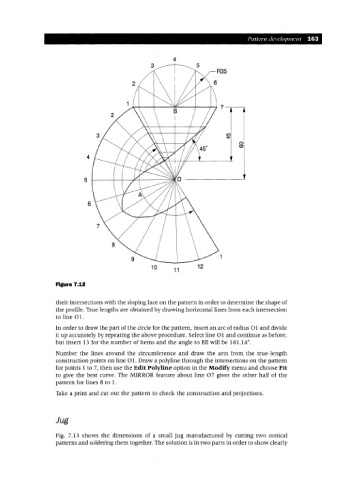
Figure 7.12
their intersections with the sloping face on the pattern in order to determine the shape of
the profile. True lengths are obtained by drawing horizontal lines from each intersection
to line 01.
In order to draw the part of the circle for the pattern, insert an arc of radius Oland divide
it up accurately by repeating the above procedure. Select line Oland continue as before,
but insert 13 for the number of items and the angle to fill will be 181.14°.
Number the lines around the circumference and draw the arcs from the true-length
construction points on line 01. Draw a polyline through the intersections on the pattern
for points 1 to 7, then use the Edit Polyline option in the Modify menu and choose Fit
to give the best curve. The MIRROR feature about line 07 gives the other half of the
pattern for lines 8 to 1.
Take a print and cut out the pattern to check the construction and projections.
Jug
Fig. 7.13 shows the dimensions of a small jug manufactured by cutting two conical
patterns and soldering them together. The solution is in two parts in order to show clearly