
Page 173 - Engineering drawing from first principles using AutoCAD
P. 173
166 Enqineerinq drawinq [rom first principles
8 .9
7
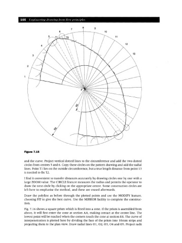
Figure 7.15
and the curve. Project vertical dotted lines to the circumference and add the two dotted
circles from centres 5 and 6. Copy these circles on the pattern drawing and add the radial
lines. Point T1lies on the outside circumference, but a true length distance from point 13
is needed to fix T2.
I find it convenient to transfer distances accurately by drawing circles one by one with a
large ZOOM value. The CIRCLE feature measures the radius and permits the operator to
draw the next circle by clicking on the appropriate centre. Some construction circles are
left here to emphasise the method, and these are erased afterwards.
Draw the polyline as before through the plotted points and use the MODIFY feature,
choosing FIT to give the best curve. Use the MIRROR facility to complete the construc-
tion.
Fig. 7.16 shows a square prism which is fitted into a cone. If the prism is assembled from
above, it will first enter the cone at section AA, making contact at the centre line. The
lowest point will be reached when the corners touch the cone at section EE. The curve of
interpenetration is plotted here by dividing the face of the prism into 10mm strips and
projecting them to the plan view. Draw radial lines 01, 02, 03, 04 and 05. Project radii