
Page 168 - Engineering drawing from first principles using AutoCAD
P. 168
Pattern development 161
---,f---------+----+-------:l~--___I-_+______r
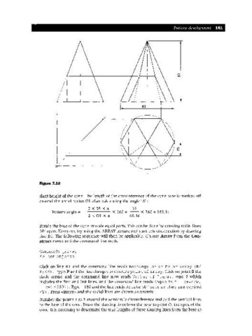
Figure 7.10
slant height of the cone. The length of the circumference of the cone base is marked off
around the arc of radius a 1 after calculating the angleA' :
2 X 35 X n
35
Pattern angle = ---- X 360 = -- X 360 = 181.14
2XOIXn 69.46
Divide the base of the cone into six equal parts. This can be done by drawing radial lines
30°apart. However, try using the ARRAY feature and start this construction by drawing
line Bl. The following sequence will then be applicable. Choose Array from the Con-
struct menu and the command line reads
Command: _array
Select obj ects
Click on line Bl and the command line reads Rectangular or Polar array (R/
P) <R>. Type P and the line changes to Centre point of array. Click on point B the
circle centre and the command line now reads Number of Items:. Type 7 which
includes the first and last lines, and the command line reads Angle to fill (+=ccw,
-=cw) <360>:. Type -180 and the line reads Rota te obj ects as they are copied
<Y>. Press <Enter> and the radial lines are drawn accurately.
Number the points 1 to 7 around the semicircle circumference and add the vertical lines
to the base of the cone. Draw the slanting lines from the base to point 0, the apex of the
cone. It is necessary to determine the true lengths of these slanting lines from the base to