
Page 248 - Engineering drawing from first principles using AutoCAD
P. 248
Technical drawings for industry 241
044
~ :
~ 010_ °LO
oq-
x
C\I
1
I
l
I n
I 0
C\I
r
~ L / ___ l
~- ~~
~
~
C")
C\I ~
C\I
C\J ,
\ ,r l'
\
-
2 ~ - ~4-WEBS
034
.:: ~ x 5 THICK
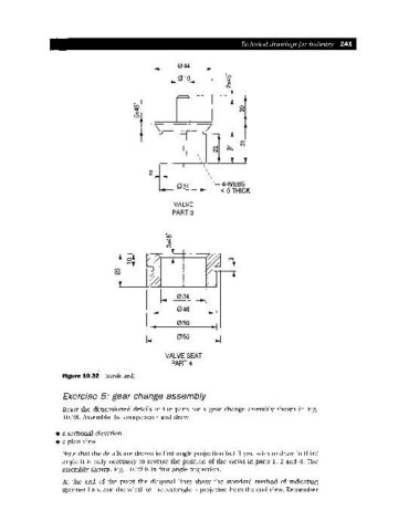
VALVE
PART 3
I.. 034 ~I
046
050
056
VALVE SEAT
PART 4
Figure 10.32 (continued)
Exercise 5: gear change assembly
Draw the dimensioned details of the parts for a gear change assembly shown in Fig.
10.28. Assemble the components and draw
• a sectional elevation
• a plan view
Note that the details are drawn in first angle projection but if you wish to draw in third
angle it is only necessary to reverse the position of the views in parts 1, 2 and 4. The
assembly shown, Fig. 10.29 is in first angle projection.
At the end of the pivot the diagonal lines show the standard method of indicating
spanner flats, and the width of the rectangle is projected from the end view. Remember