
Page 246 - Engineering drawing from first principles using AutoCAD
P. 246
Technical drawinqs for industry 239
addition. Position the part numbers in as neat a way as possible and symmetrically if you
can. Figure 10.23 shows the completed first angle projection.
The draughtsman will select sectional views which clearly show the way components are
assembled, and as many views as are necessary for clarity.
Exercise 3: lever assembly
Three parts in a lever assembly are detailed in Fig. 10.24. Copy the details and draw a
sectional elevation and plan view (Fig. 10.25). Note there are four holes on the pivot base.
In order to speed up your draughting, it is only necessary to draw one hole complete with
centre lines and then copy the others three. The screw threads are engaged, so cross-
hatching does not cover the area between the major and minor diameters. Use a radius of
3mm for all of the fillet radii. Assemble using COpy and MOVE and remove unwanted
linework.
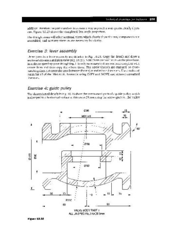
Exercise 4: guide pulley
The dimensioned details in Fig. 10.26 show the component parts of a guide pulley which
is clamped to a horizontal surface of thickness 25 mm using the screw (part 3). The pulley
096 15
M64 xs ~I
~I
-- --
---...
o o
C\I co _ - - - - - --+ T"---+-----7'-~--+----+----........,..,_:.,L-7"'-++
lS)
35 10 10 35
R110
80 80
VALVE BODYPART 1
ALL UNSPECIFIED RADII3mm
Figure 10.32