
Page 59 - Engineering drawing from first principles using AutoCAD
P. 59
52 Engineering drawinq [1"0111 first principles
When using the FILLET feature you will find that one line is deleted which is required for
the next step. This can easily be replaced using the EXTEND option. Line in the outlines
with polylines of thickness O.4mm as shown in Fig. 2.25.
Gear wheel assembly
Fig. 2.26 shows the assembly of two gear wheels in mesh and notes associated with this
branch of technology. Fig. 2.27 gives dimensions of the shaft details and tooth profile.
Draw the assembly using the following procedure.
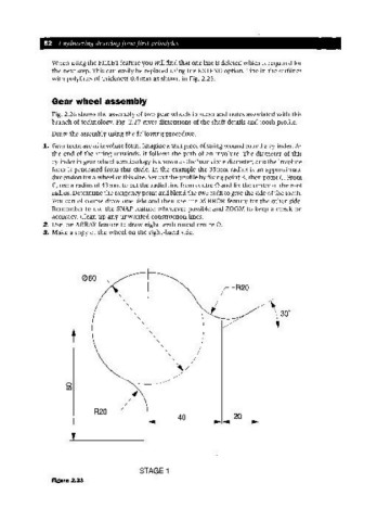
1. Gear teeth are of involute form. Imagine a taut piece of string wound round a cylinder. As
the end of the string unwinds, it follows the path of an involute. The diameter of this
cylinder in gear wheel terminology is known as the base circle diameter, and the involute
form is generated from this circle. In the example the 3Smm radius is an approximate
dimension for a wheel of this size. Set out the profile by fixing point B, then point C. From
C, use a radius of 43 mm to cut the radial line from centre 0 and fix the centre of the root
radius. Determine the tangency point and blend the two radii to give the side of the tooth.
You can of course draw one side and then use the MIRROR feature for the other side.
.Remember to use the SNAP feature whenever possible and ZOOM to keep a check on
accuracy. Clean up any unwanted construction lines.
2. Use the ARRAY feature to draw eight teeth round centre o.
3. Make a copy of the wheel on the right-hand side.
060
-R20
o
to
R20~
40 20
STAGE 1
Figure 2.23