
Page 64 - Engineering drawing from first principles using AutoCAD
P. 64
Geometrical applications 57
10
~
~R35
R75
OUTSIDE DIAMETER
/~ R58
BASE CIRCLE
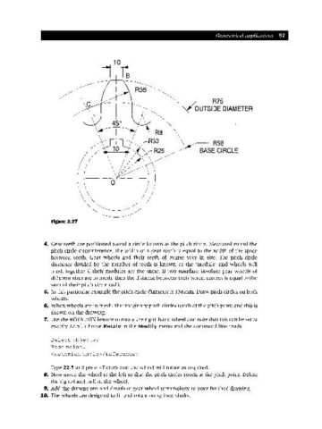
Figure 2.27
4. Gear teeth are positioned round a circle known as the pitch circle. Measured round the
pitch circle circumference, the width of a gear tooth is equal to the width of the space
between teeth. Gear wheels and their teeth of course vary in size. The pitch circle
diameter divided by the number of teeth is known as the 'module' and wheels will
mesh together if their modules are the same. If two standard involute gear wheels of
different sizes are in mesh, then the distance between their wheel centres is equal to the
sum of their pitch circle radii.
5. In this particular example the pitch circle diameter is 136mm. Draw pitch circles on both
wheels.
6. When wheels are in mesh, the imaginary pitch circles touch at the pitch point and this is
shown on the drawing.
7. Use the ROTATION feature to rotate the right-hand wheel and note that this can be set at
exactly 22.5°. Choose Rotate in the Modify menu and the command line reads
Select obj ects:
Base point:
<Rotation angle>/Reference:
Type 22.5 and press <Enter> and the wheel will rotate as required.
B. Now move the wheel to the left so that the pitch circles touch at the pitch point. Delete
the right-hand half of the wheel.
9. Add the dimensions and details of gear wheel terminology to your finished drawing.
10. The wheels are designed to fit and rotate on splined shafts.