
Page 68 - Engineering drawing from first principles using AutoCAD
P. 68
Geometrical applications 61
A
c 40 120
R96
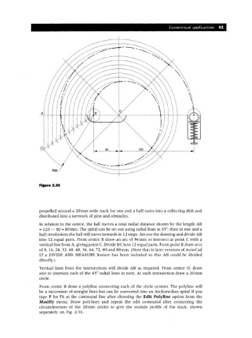
Figure 2.30
propelled around a 20mm wide track for one and a half turns into a collecting dish and
distributed into a network of pins and obstacles.
In relation to the centre, the ball moves a total radial distance shown by the length AB
= 120 - 40 = 80mm. The spiral can be set out using radial lines at 45°, then in one and a
half revolutions the ball will move inwards in 12 steps. Set out the drawing and divide AB
into 12 equal parts. From centre B draw an arc of 96mm to intersect at point C with a
vertical line from A, giving point C. Divide BC into 12 equal parts. From point B draw arcs
of 8, 16,24,32,40,48, 56,64,72,80 and 88mm. (Note that in later versions of AutoCad
LT a DIVIDE AND MEASURE feature has been included so that AB could be divided
directly.)
Vertical lines from the intersections will divide AB as required. From centre 0, draw
arcs to intersect each of the 45° radial lines in turn. At each intersection draw a 20mm
circle.
From centre B draw a polyline connecting each of the circle centres. The polyline will
be a succession of straight lines but can be converted into an Archimedian spiral if you
type F for Fit at the command line after choosing the Edit Polyline option from the
Modify menu. Draw polylines and repeat the edit command after connecting the
circumferences of the 20mm circles to give the outside profile of the track, shown
separately on Fig. 2.31.