
Page 69 - Engineering drawing from first principles using AutoCAD
P. 69
62 Engineering drawing front first principles
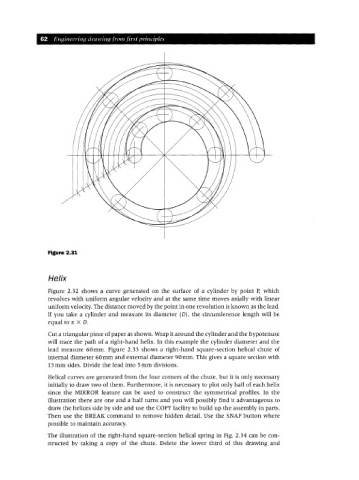
Figure 2.31
Helix
Figure 2.32 shows a curve generated on the surface of a cylinder by point P, which
revolves with uniform angular velocity and at the same time moves axially with linear
uniform velocity. The distance moved by the point in one revolution is known as the lead.
If you take a cylinder and measure its diameter (D), the circumference length will be
equal to 1t X D.
Cut a triangular piece of paper as shown. Wrap it around the cylinder and the hypotenuse
will trace the path of a right-hand helix. In this example the cylinder diameter and the
lead measure 60mm. Figure 2.33 shows a right-hand square-section helical chute of
internal diameter 60mm and external diameter 90mm. This gives a square section with
15 mm sides. Divide the lead into 5mm divisions.
Helical curves are generated from the four corners of the chute, but it is only necessary
initially to draw two of them. Furthermore, it is necessary to plot only half of each helix
since the MIRROR feature can be used to construct the symmetrical profiles. In the
illustration there are one and a half turns and you will possibly find it advantageous to
draw the helices side by side and use the COpy facility to build up the assembly in parts.
Then use the BREAI( command to remove hidden detail. Use the SNAP button where
possible to maintain accuracy.
The illustration of the right-hand square-section helical spring in Fig. 2.34 can be con-
structed by taking a copy of the chute. Delete the lower third of this drawing and