
Page 26 - Enhanced Oil Recovery in Shale and Tight Reservoirs
P. 26
16 Enhanced Oil Recovery in Shale and Tight Reservoirs
Figure 2.7 Schematic of the displacement equipment (Tovar et al., 2014).
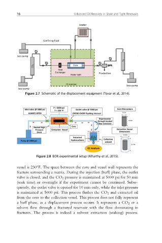
Figure 2.8 EOR experimental setup (Alharthy et al., 2015).
vessel is 230 F. The space between the core and vessel wall represents the
fracture surrounding a matrix. During the injection (huff) phase, the outlet
valve is closed, and the CO 2 pressure is maintained at 5000 psi for 50 min
(soak time) or overnight if the experiment cannot be continued. Subse-
quently, the outlet valve is opened for 10 min only, while the inlet pressure
is maintained at 5000 psi. This process flushes the CO 2 and extracted oil
from the core to the collection vessel. This process does not fully represent
a huff phase, as a displacement process occurs. It represents a CO 2 or a
solvent flow through a fractured reservoir with the flow dominating in
fractures. The process is indeed a solvent extraction (soaking) process.