
Page 105 - Facility Piping Systems Handbook for Industrial, Commercial, and Healthcare Facilities
P. 105
PIPING
PIPING 2.55
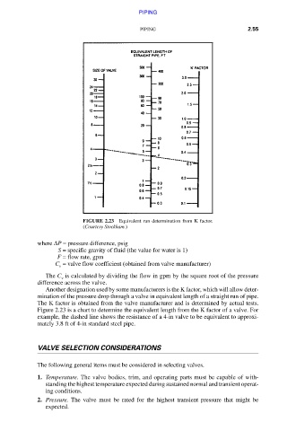
FIGURE 2.23 Equivalent run determination from K factor.
(Courtesy Stockham.)
where ΔP = pressure difference, psig
S = specific gravity of fluid (the value for water is 1)
F = flow rate, gpm
C = valve flow coefficient (obtained from valve manufacturer)
v
The C is calculated by dividing the flow in gpm by the square root of the pressure
v
difference across the valve.
Another designation used by some manufacturers is the K factor, which will allow deter-
mination of the pressure drop through a valve in equivalent length of a straight run of pipe.
The K factor is obtained from the valve manufacturer and is determined by actual tests.
Figure 2.23 is a chart to determine the equivalent length from the K factor of a valve. For
example, the dashed line shows the resistance of a 4-in valve to be equivalent to approxi-
mately 3.8 ft of 4-in standard steel pipe.
VALVE SELECTION CONSIDERATIONS
The following general items must be considered in selecting valves.
1. Temperature. The valve bodies, trim, and operating parts must be capable of with-
standing the highest temperature expected during sustained normal and transient operat-
ing conditions.
2. Pressure. The valve must be rated for the highest transient pressure that might be
expected.
Downloaded from Digital Engineering Library @ McGraw-Hill (www.accessengineeringlibrary.com)
Copyright © 2009 The McGraw-Hill Companies. All rights reserved.
Any use is subject to the Terms of Use as given at the website.