
Page 109 - Facility Piping Systems Handbook for Industrial, Commercial, and Healthcare Facilities
P. 109
PIPING
PIPING 2.59
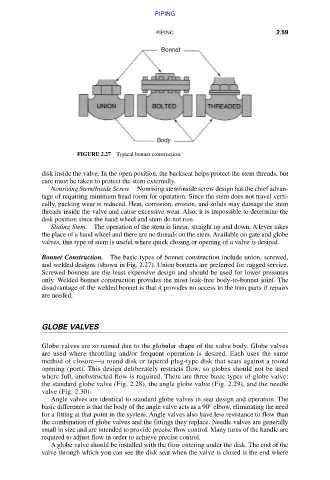
FIGURE 2.27 Typical bonnet construction.
disk inside the valve. In the open position, the backseat helps protect the stem threads, but
care must be taken to protect the stem externally.
Nonrising Stem/Inside Screw. Nonrising stem/inside screw design has the chief advan-
tage of requiring minimum head room for operation. Since the stem does not travel verti-
cally, packing wear is reduced. Heat, corrosion, erosion, and solids may damage the stem
threads inside the valve and cause excessive wear. Also, it is impossible to determine the
disk position since the hand wheel and stem do not rise.
Sliding Stem. The operation of the stem is linear, straight up and down. A lever takes
the place of a hand wheel and there are no threads on the stem. Available on gate and globe
valves, this type of stem is useful where quick closing or opening of a valve is desired.
Bonnet Construction. The basic types of bonnet construction include union, screwed,
and welded designs (shown in Fig. 2.27). Union bonnets are preferred for rugged service.
Screwed bonnets are the least expensive design and should be used for lower pressures
only. Welded bonnet construction provides the most leak-free body-to-bonnet joint. The
disadvantage of the welded bonnet is that it provides no access to the trim parts if repairs
are needed.
GLOBE VALVES
Globe valves are so named due to the globular shape of the valve body. Globe valves
are used where throttling and/or frequent operation is desired. Each uses the same
method of closure—a round disk or tapered plug-type disk that seats against a round
opening (port). This design deliberately restricts flow, so globes should not be used
where full, unobstructed flow is required. There are three basic types of globe valve:
the standard globe valve (Fig. 2.28), the angle globe valve (Fig. 2.29), and the needle
valve (Fig. 2.30).
Angle valves are identical to standard globe valves in seat design and operation. The
basic difference is that the body of the angle valve acts as a 90° elbow, eliminating the need
for a fitting at that point in the system. Angle valves also have less resistance to flow than
the combination of globe valves and the fittings they replace. Needle valves are generally
small in size and are intended to provide precise flow control. Many turns of the handle are
required to adjust flow in order to achieve precise control.
A globe valve should be installed with the flow entering under the disk. The end of the
valve through which you can see the disk seat when the valve is closed is the end where
Downloaded from Digital Engineering Library @ McGraw-Hill (www.accessengineeringlibrary.com)
Copyright © 2009 The McGraw-Hill Companies. All rights reserved.
Any use is subject to the Terms of Use as given at the website.