
Page 246 - Facility Piping Systems Handbook for Industrial, Commercial, and Healthcare Facilities
P. 246
HEAT TRANSFER, INSULATION, AND FREEZE PROTECTION
5.30 CHAPTER FIVE
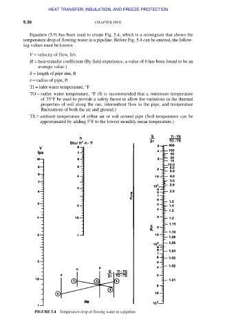
Equation (5.9) has been used to create Fig. 5.4, which is a nomogram that shows the
temperature drop of flowing water in a pipeline. Before Fig. 5.4 can be entered, the follow-
ing values must be known:
V = velocity of flow, ft/s
H = heat-transfer coefficient (By field experience, a value of 6 has been found to be an
average value.)
S = length of pipe run, ft
r = radius of pipe, ft
TI = inlet water temperature, °F
TO = outlet water temperature, °F (It is recommended that a minimum temperature
of 35°F be used to provide a safety factor to allow for variations in the thermal
properties of soil along the run, intermittent flow in the pipe, and temperature
fluctuations of both the air and ground.)
TS = ambient temperature of either air or soil around pipe (Soil temperature can be
approximated by adding 5°F to the lowest monthly mean temperature.)
FIGURE 5.4 Temperature drop of flowing water in a pipeline.
Downloaded from Digital Engineering Library @ McGraw-Hill (www.accessengineeringlibrary.com)
Copyright © 2009 The McGraw-Hill Companies. All rights reserved.
Any use is subject to the Terms of Use as given at the website.