
Page 292 - Facility Piping Systems Handbook for Industrial, Commercial, and Healthcare Facilities
P. 292
SITE UTILITY SYSTEMS
6.14 CHAPTER SIX
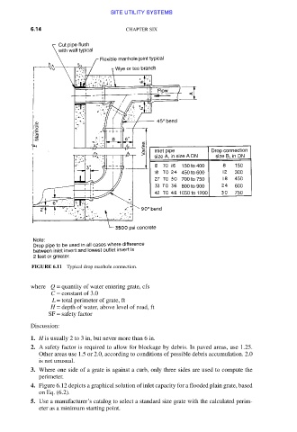
FIGURE 6.11 Typical drop manhole connection.
where Q = quantity of water entering grate, cfs
C = constant of 3.0
L = total perimeter of grate, ft
H = depth of water, above level of road, ft
SF = safety factor
Discussion:
1. H is usually 2 to 3 in, but never more than 6 in.
2. A safety factor is required to allow for blockage by debris. In paved areas, use 1.25.
Other areas use 1.5 or 2.0, according to conditions of possible debris accumulation. 2.0
is not unusual.
3. Where one side of a grate is against a curb, only three sides are used to compute the
perimeter.
4. Figure 6.12 depicts a graphical solution of inlet capacity for a flooded plain grate, based
on Eq. (6.2).
5. Use a manufacturer’s catalog to select a standard size grate with the calculated perim-
eter as a minimum starting point.
Downloaded from Digital Engineering Library @ McGraw-Hill (www.accessengineeringlibrary.com)
Copyright © 2009 The McGraw-Hill Companies. All rights reserved.
Any use is subject to the Terms of Use as given at the website.