
Page 348 - Facility Piping Systems Handbook for Industrial, Commercial, and Healthcare Facilities
P. 348
SITE UTILITY SYSTEMS
6.70 CHAPTER SIX
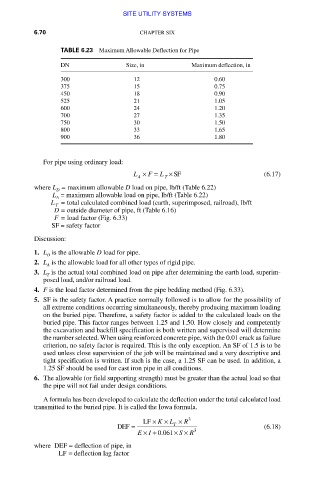
TABLE 6.23 Maximum Allowable Deflection for Pipe
DN Size, in Maximum deflection, in
300 12 0.60
375 15 0.75
450 18 0.90
525 21 1.05
600 24 1.20
700 27 1.35
750 30 1.50
800 33 1.65
900 36 1.80
For pipe using ordinary load:
L × F = L × SF (6.17)
A T
where L = maximum allowable D load on pipe, lb/ft (Table 6.22)
D
L = maximum allowable load on pipe, lb/ft (Table 6.22)
A
L = total calculated combined load (earth, superimposed, railroad), lb/ft
T
D = outside diameter of pipe, ft (Table 6.16)
F = load factor (Fig. 6.33)
SF = safety factor
Discussion:
1. L is the allowable D load for pipe.
D
2. L is the allowable load for all other types of rigid pipe.
A
3. L is the actual total combined load on pipe after determining the earth load, superim-
T
posed load, and/or railroad load.
4. F is the load factor determined from the pipe bedding method (Fig. 6.33).
5. SF is the safety factor. A practice normally followed is to allow for the possibility of
all extreme conditions occurring simultaneously, thereby producing maximum loading
on the buried pipe. Therefore, a safety factor is added to the calculated loads on the
buried pipe. This factor ranges between 1.25 and 1.50. How closely and competently
the excavation and backfill specification is both written and supervised will determine
the number selected. When using reinforced concrete pipe, with the 0.01 crack as failure
criterion, no safety factor is required. This is the only exception. An SF of 1.5 is to be
used unless close supervision of the job will be maintained and a very descriptive and
tight specification is written. If such is the case, a 1.25 SF can be used. In addition, a
1.25 SF should be used for cast iron pipe in all conditions.
6. The allowable (or field supporting strength) must be greater than the actual load so that
the pipe will not fail under design conditions.
A formula has been developed to calculate the deflection under the total calculated load
transmitted to the buried pipe. It is called the Iowa formula.
LF × K × L × R 3
DEF = T 3 (6.18)
I
E ×+ 0 061. × × R
S
where DEF = deflection of pipe, in
LF = deflection lag factor
Downloaded from Digital Engineering Library @ McGraw-Hill (www.accessengineeringlibrary.com)
Copyright © 2009 The McGraw-Hill Companies. All rights reserved.
Any use is subject to the Terms of Use as given at the website.