
Page 263 - Failure Analysis Case Studies II
P. 263
248
one end to secure the driven timing belt pulley wheel. The ends of the shaft are reduced in diameter
(to nominally 12 mm diameter along a 76 mm length with 3 mm fillet radius at the shoulder) and
act as hubs for mounting the 150 mm diameter wheels (which are shrink-fitted onto 76 mm long
sleeves) as shown in Fig. 2. A keyway slot runs 73 mm along the length of the 12 mm hub diameter
and a M6 screw fits in the sleeve to secure the wheel from moving axially along the shaft as more
clearly illustrated in Fig. 3.
3. ASSESSING THE FAILURE
The failed wheel shaft had broken in two, having separated close to the end of the keyway slot
on one of the 12 mm diameter hubs-approximately 73 mm from one end, as shown in Fig. 2. A
fatigue crack is clearly evident for about half of the broken sectional area (that nearest to the keyway
groove) as the characteristic circular lines radiating outwards from the corner of the keyway are
clearly visible. The remaining section failed through static fracture-being insufficient to support
the loads. From observation of the failed shaft it is not evident whether shaft bending or torsion is
the primary cause or whether it is a combination of the two and so analysis is necessary.
4. SHAFT ANALYSIS
Because it is not immediately obvious whether bending or torsion has been the major cause of
failure, both effects are considered independently.
4.1. Bending under static loading
The trolley weight (with annour plate), W = 320 kg (3.2 kN) and is assumed to be evenly shared
among the four wheels. The bending moment occurring along the shaft may simply be determined
from taking the product of the wheel reaction force and the moment arm (from wheel centre to
location of interest).
At end of keyway, bending moment,
W
M = - (73 mm-30 mm) = 34.4 Nm.
x
4
II 4-1
I1 Ilh
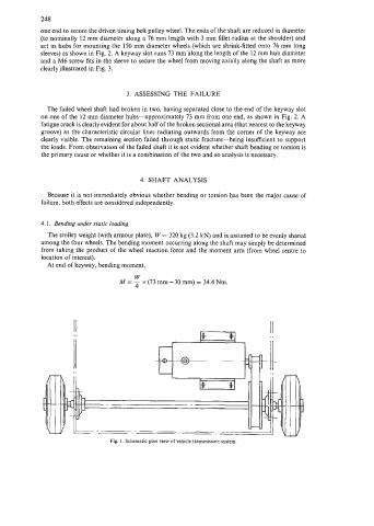
Fig. 1. Schematic plan view of vehicle transmission system.