
Page 266 - Failure Analysis Case Studies II
P. 266
25 1
4.3. Material fatigue strength
Grade 316 stainless steel grade is used for the shaft and the following material data is obtained
from Appendix B of Ref. 3 and stress concentration factor data also from Appendix C of Ref. [3]:
Tensile strength, = 552 MN/m2.
Unnotched bending fatigue strength, 6, = 262 MN/mZ (at IO' cycles).
Stress concentration factor at end of keyway, KT = 1.9 (shaft with radial hole chart d/D = 4/12).
Stress concentration factor at change of dia., KT = 1.4 (stepped diameter with fillet r/D = 3/12).
Working cndurance limit, u, = 262/1.9 MN/m2 = 138 MN/m2.
This last value is approximate and is quoted for guidance purposes and will be even lower if surface
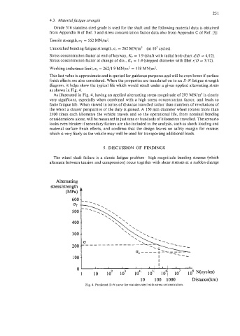
finish effects are also considered. When the properties are translated on to an S-N fatigue strength
diagram, it helps show the typical life which would result under a given applied alternating stress
as shown in Fig. 4.
As illustrated in Fig. 4, having an applied alternating stress magnitude of 203 MN/mZ is clearly
very significant, especially when combined with a high stress concentration factor, and leads to
finite fatigue life. When viewed in terms of distance travelled rather than numbers of revolutions of
the wheel a clearer perspective of the duty is gained. A 150 mm diameter wheel rotates more than
2 100 times each kilometre the vehicle travels and so the operational life, from nominal bending
considerations alone, will be measured in just tens or hundreds of kilometres travelled. The scenario
looks even bleaker if secondary factors are also included in the analysis, such as shock loading and
material surface finish effects, and confirms that the design leaves no safety margin for misuse;
which is very likely as the vehicle may well be used for transporting additional loads.
5. DISCUSSION OF FINDINGS
The wheel shaft failure is a classic fatigue problem-high magnitude bending stresses (which
alternate between tension and compression) occur together with shear stresses at a sudden change
Alternating
(MW t
stresslstrength
600
=T
500
400
300
200
100
I I I I I;II. I I
1 IO lo2 lo3 10'' losi lo6/ 10' lo8 N(cyc1es)
10 100 1000 Distance(km)
Fig. 4. Predicted S-N curve for stainless steel with stress concentration.