
Page 328 - Failure Analysis Case Studies II
P. 328
Failure Analysis Case Studies II
D.R.H. Jones (Editor)
0 200 1 Elsevier Science Ltd. All rights reserved 313
CORROSION OF FLEXIBLE WAVEGUIDES
D. PAPATHEODOROU, M. SMITH and 0. S. ES-SAID*
Mechanical Engineering Department, Loyola Marymount University, 7900 Loyola Blvd, Los Angeles,
CA 90045-8145, U.S.A.
(Received 9 August 1997)
Abstract-Waveguides are commonly used in spacecraft subsystems to convey signals. After noticing a
transponder ouput power drop, borescope inspection of a flexible waveguide revealed a green contaminating
residue on silver plated brass and copper sections. Analysis revealed that the residue, primarily copper hydroxy
nitrate, Cu(OH),N03, was created by exposure of the plating to nitric acid. Possible sources of nitric acid
include inadequate cleanliness after parts were exposed to a nitric acid containing silver bright dip, or high
temperature electrical arcing in the presence of air and moisture. Whatever its source, it is suggested that the
waveguide be plated with a more corrosion resistant metal such as rhodium. 0 1998 Elsevier Science Ltd. All
rights reserved.
Keywords: Corrosion, electronic-device failures, surface coatings.
1. INVESTIGATION
Flexible waveguides, common in spacecraft payload sub-systems, transport signals between various
units (e.g., filters, transponders, and converters). During preliminary testing at ambient temperature
and pressure, an output power drop was detected within a signal generating unit of a waveguide
system. Green contamination residue was found in the waveguides. An investigation commenced
to characterize the corrosion and determine its cause.
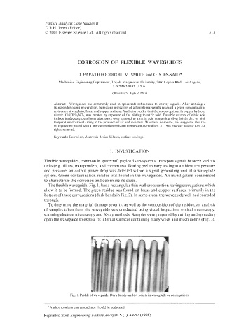
The flexible waveguide, Fig. 1, has a rectangular thin wall cross section having corrugations which
allow it to be formed. The green residue was found on brass and copper surfaces, primarily in the
bottom of those corrugations (dark bands in Fig. 2). In some areas, the waveguide wall had corroded
through.
To determine the material damage severity, as well as the composition of the residue, an analysis
of samples taken from the waveguide was conducted using visual inspection, optical microscopy,
scanning electron microscopy and X-ray methods. Samples were prepared by cutting and spreading
open the waveguide to expose its internal surfaces containing many voids and much debris (Fig. 3).
Fig. 1. Profile of waveguide. Dark bands are low points in waveguide or corrugations
*Author to whom correspondence should be addressed.
Reprinted from Engineering Failure Analysis 5 (l), 49-52 (1998)