
Page 347 - Failure Analysis Case Studies II
P. 347
332
Cracked region
Burner
\ support A
a) Top View
b) Side View
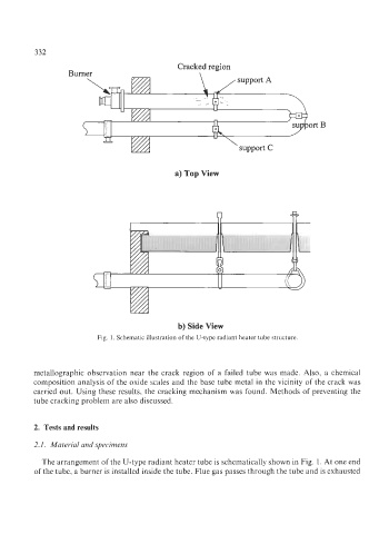
Fig. 1. Schematic illustration of the U-type radiant heater tube structure.
metallographic observation near the crack region of a failed tube was made. Also, a chemical
composition analysis of the oxide scales and the base tube metal in the vicinity of the crack was
carried out. Using these results, the cracking mechanism was found. Methods of preventing the
tube cracking problem are also discussed.
2. Tests and results
2.1. Material and specimens
The arrangement of the U-type radiant heater tube is schematically shown in Fig. 1. At one end
of the tube, a burner is installed inside the tube. Flue gas passes through the tube and is exhausted