
Page 348 - Failure Analysis Case Studies II
P. 348
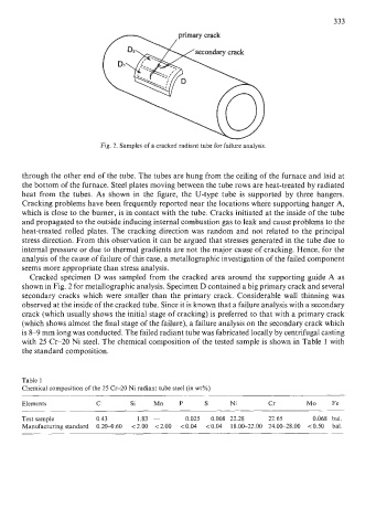
333
                                                   primary crack

                                                        secondary crack


                             Fig. 2. Samples of a cracked radiant tube for failure analysis.


       through the other end of the tube. The tubes are hung from the ceiling of the furnace and laid at
       the bottom of the furnace. Steel plates moving between the tube rows are heat-treated by radiated
       heat  from  the  tubes. As  shown in  the figure, the  U-type tube is  supported  by  three hangers.
       Cracking problems have been frequently reported near the locations where supporting hanger A,
       which is close to the burner, is in contact with the tube. Cracks initiated at the inside of the tube
       and propagated to the outside inducing internal combustion gas to leak and cause problems to the
       heat-treated  rolled plates. The cracking direction was random and not related to the principal
       stress direction. From this observation it can be argued that stresses generated in the tube due to
       internal pressure or due to thermal gradients are not the major cause of cracking. Hence, for the
       analysis of the cause of failure of this case, a metallographic investigation of the failed component
       seems more appropriate than stress analysis.
         Cracked specimen D was sampled from the cracked area around the supporting guide A as
       shown in Fig. 2 for metallographic analysis. Specimen D contained a big primary crack and several
       secondary cracks which were smaller than  the primary crack. Considerable wall  thinning was
       observed at the inside of the cracked tube. Since it is known that a failure analysis with a secondary
       crack (which usually shows the initial stage of cracking) is preferred to that with a primary crack
       (which shows almost the final stage of the failure), a failure analysis on the secondary crack which
       is 8-9  mm long was conducted. The failed radiant tube was fabricated locally by centrifugal casting
       with 25 Cr-20  Ni steel. The chemical composition of the tested sample is shown in Table 1 with
       the standard composition.


       Table 1
       Chemical composition of the 25 Cr-20  Ni radiant tube steel (in wt%)
       ~~       ~~~   ~~~
       Elements             C         Si    Mn     P      S      Ni         Cr         Mo     Fe
       Test sample          0.43        1.83  -      0.025   0.008  22.28   22.65        0.068  bal.
       Manufacturing standard  0.20-0.60   <2.00   ~2.00  <0.04   <0.04   18.00-22.00  24.00-28.00  <OS0  bal.