
Page 392 - Failure Analysis Case Studies II
P. 392
377
during the PWHT of the very heavy section nozzle forging. Contributory factors would have been
the high stress concentration at the toe of the weld, a degree of tri-axial stress resulting from the
thick section geometry in this area, and an over-matching of mechanical properties of the filler
metal. It is possible that the re-heat cracking may have occurred during service, but it is considered
to be unlikely as the normal operating temperature of 385°C is believed to be too low to initiate the
mechanism.
The possibility of some delayed cold-cracking in the HAZ cannot be ruled out in view of the
protracted delay between welding and PWHT, and if present, would also have assisted in the
nucleation of the reheat cracking.
Unfortunately it was impractical to weld these materials with a lower-strength filler metal since
the lowest strength Cr-Mo filler specified under ASME I1 SFA 5.5 has a minimum UTS of 80,000
p.s.i. The following measures were included in the repair procedure for the nozzle:
(a) Pre-heat temperature was increased from 150°C as used in the original fabrication, to 200-
250°C.
(b) Pre-heat was maintained until PWHT was carried out.
(c) The weld toe was dressed to a generous transition radius.
3. CASE 2-EXAMINATION OF CRACKS IN EXTERNAL SUPPORT RING
3.1. Visual examination
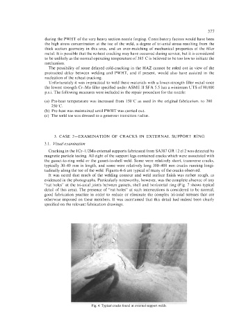
Cracking in the lCr-l/2Mo external supports fabricated from SA387 GR 12 cl2 was detected by
magnetic particle testing. All eight of the support legs contained cracks which were associated with
the gusset-to-ring weld or the gusset-to-shell weld. Some were relatively short, transverse cracks,
typically 3WO mm in length, and some were relatively long 30WOO mm cracks running longi-
tudinally along the toe of the weld. Figures 4-6 are typical of many of the cracks observed.
It was noted that much of the welding contour and weld surface finish was rather rough, as
evidenced in the photographs. Particularly noteworthy, however, was the complete absence of any
“rat holes” at the tri-axial joints between gussets, shell and horizontal ring (Fig. 7 shows typical
detail of this area). The presence of “rat holes” at such intersections is considered to be normal,
good fabrication practice in order to reduce or eliminate the complex tri-axial stresses that are
otherwise imposed on these members. It was ascertained that this detail had indeed been clearly
specified on the relevant fabrication drawings.
Fig. 4. Typical cracks found at external support welds