
Page 433 - Failure Analysis Case Studies II
P. 433
417
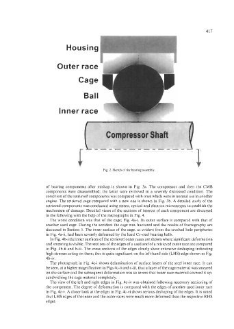
Housing
Inner ra
Fig. 2. Sketch of the bearing assembly.
of bearing components after mishap is shown in Fig. 3a. The compressor and then the CMB
components were disassembled; the latter were retrieved in a severely distressed condition. The
condition of the retrieved components was compared with ones which were in normal use in another
engine. The retrieved cage compared with a new one is shown in Fig. 3b. A detailed study of the
retrieved components was conducted using stereo, optical and electron microscopes to establish the
mechanism of damage. Detailed views of the sections of interest of each component are discussed
in the following with the help of the micrographs in Fig. 4.
The worst condition was that of the cage; Fig. 4a-i. Its outer surface is compared with that of
another used cage. During the accident the cage was fractured and the results of fractography are
discussed in Section 3. The inner surface of the cage, as evident from the crushed hole peripheries
in Fig. 4a-ii, had been severely deformed by the hard Cr-steel bearing balls.
In Fig. 4b-i the inner surfaces of the retrieved outer races are shown where significant deformation
and smearing is visible. The sections of the edges of a used and of a retrieved outer race are compared
in Fig. 4b-ii and b-iii. The cross sections of the edges clearly show extensive deshaping indicating
high stresses acting on them; this is quite significant on the left-hand side (LHS) edge shown in Fig.
4b-iv.
The photograph in Fig. 4c-i shows delamination of surface layers of the steel inner race. It can
be seen, at a higher magnification in Figs 4c-ii and c-iii, that a layer of the cage material was smeared
on the surface and the subsequent deformation was so severe that inner race material covered it up,
sandwiching the cage material completely.
The view of the left and right edges in Fig. 4c-iv was obtained following necessary sectioning of
the component. The degree of deformation is compared with the edges of another used inner race
in Fig. 4c-v. A closer look at the edges in Fig. 4c-vi shows serious deshaping of the edges. It is noted
that LHS edges of the inner and the outer races were much more deformed than the respective RHS
edges.