
Page 46 - Failure Analysis Case Studies II
P. 46
32
k
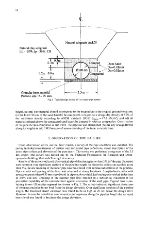
Natural clay subgrade
LL - 62%; Ip - 36%; CH
Granular base mat
Particle size 16 - 20 mm.
Fig. I, Typical design section of the trench-pipe system.
height, natural clay material should be returned to the excavation to the original ground elevation;
(c) the lower 90 cm of the sand backfill be compacted in layers to a design dry density of 95% of
the maximum density according to ASTM standard D1557 (ydmax = 17.1 kN/m’); and (d) all
materials placed above the compacted sand layers be dumped in without compaction. Construction
of the pipeline was completed in mid 1994. The pipeline was abandoned (before any sewage flowed
along its length) in mid 1995 because of severe cracking of the inner concrete liner.
3. OBSERVATION OF PIPE FAILURE
Upon observation of the internal liner cracks, a survey of the pipe condition was initiated. The
survey included measurement of vertical and horizontal pipe deflections, visual description of the
inner pipe surface and elevation of the pipe invert. The survey was performed along most of the 3.5
km length. The survey was carried out by the Technion Foundation for Research and Devel-
opment-Building Materials Testing Laboratory.
Results of the survey indicated that vertical pipe deflections greater than 3% (of the pipe diameter)
were common over significant sections of the pipeline length. In places the deflections reached more
than 8%. Severe cracking of the inner pipe liner was noted over substantial sections of the pipeline.
Open cracks and peeling of the liner was observed at many locations. Longitudinal cracks with
apertures greater than 0.35 mm were found in pipe sections which had undergone vertical deflections
of 2.0% and less. Cracking of the internal pipe liner resulted in a substantial reduction in the
protective capability of the concrete liner against corrosion of the steel pipe. Typical results per-
taining to one 120 m pipe segment are shown in Fig. 2. The survey indicated significant deviations
of the measured pipe invert level from the design elevation. Over significant portions of the pipeline
length, the measured invert elevation was found to be as high as 25 cm below the design level.
However, it must be noted that over several other segments along the pipeline length the surveyed
invert level was found to be above the design elevation.