
Page 41 - Failure Analysis Case Studies II
P. 41
27
and fracture. An equivalent mass factor takes account of the lower velocity of the edges than the
sides.
The first part of the response is elastic up to first yield in the frame bolts: the solution is a
relationship between displacement and time, and the initial conditions are zero displacement and
zero velocity at the start of the pulse. The second part of the response is plastic: the solution is
another relationship between displacement and time, with two integration constants determined by
matching the solutions for the first and second parts of the response.
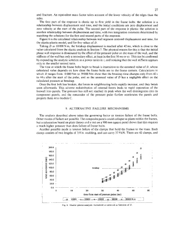
Figure 6 is the calculated relationship between wall segment centroid displacement and time, for
the elastic-plastic model, and for five values of D.
Taking D as 10000Nm, the breakup displacement is reached after 42ms, which is close to the
value calculated from the elastic analysis in Section 7. The physical reason for this is that the initial
phase wall response is dominated by the effect of the pressure pulse on the mass of the wall, and the
stiffness of the wall has only a secondary effect, at least in the first 50 ms or so. This can be confirmed
by expanding the analytic solution as a power series in t, and noticing that the wall stiffness appears
only in the smaller second term.
The time at which the frame bolts begin to break is insensitive to the assumed value of D, whose
calculated value depends on how close the frame bolts are to the frame corners. Calculations in
which D ranges from 10 000 Nm to 39 000 Nm show that the breakup time changes only from 42 s
to 44s after the start of the pulse, and so the assumed value of D has a negligible effect on the
calculated pressure at breakup.
Once the first bolt has broken, the forces in neighbouring bolts rapidly increase, and they break
soon afterwards. This adverse redistribution of internal forces leads to rapid separation of the
firewall into panels. The pressure has still not reached its peak when the wall disintegrates into its
component panels, and the remainder of the pressure pulse further accelerates the panels and
projects them into module C.
9. ALTERNATIVE FAILURE MECHANISMS
The analysis described above takes the governing factor as tension failure of the frame bolts.
Other modes of failure are possible. The composite panels could collapse as plates within the frames,
but a calcuiation based on plate theory and a test on a 900 mm square panel shows that this requires
a much higher pressure than does failure of frame bolts.
Another possible mode is tension failure of the clamps that hold the frames to the truss. Each
clamp consists of two lengths of 3/8 in. studding, and can carry 37.9 kN. There are 42 clamps, and
. ...... ........... ......
Q
8 80.0
80.0
.d
40.0
20.0
0 10 20 30 40 50 60 ,
time from start of pressure pulse (ms)
I _. -. -. _-
I '---e- .!-000Z%*P_r_"r2- -30000 -39000,!!! . --.:7
.
L ....... ~
Fig. 6. Elastic-plastic analysis: movement at centroid as function of D.