
Page 36 - Failure Analysis Case Studies II
P. 36
- I
-230 -100 300 4
n
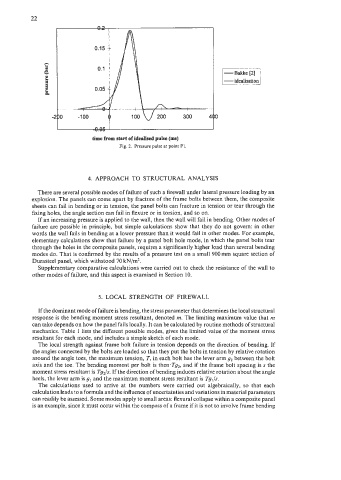
time from start of idealised pulse (ms)
Fig. 2. Pressure pulse at point PI.
4. APPROACH TO STRUCTURAL ANALYSIS
There are several possible modes of failure of such a firewall under lateral pressure loading by an
explosion. The panels can come apart by fracture of the frame bolts between them, the composite
sheets can fail in bending or in tension, the panel bolts can fracture in tension or tear through the
fixing holes, the angle section can fail in flexure or in torsion, and so on.
If an increasing pressure is applied to the wall, then the wall will fail in bending. Other modes of
failure arc possible in principle, but simple calculations show that they do not govern: in other
words the wall fails in bending at a lower pressure than it would fail in other modes. For example,
elementary calculations show that failure by a panel bolt hole mode, in which the panel bolts tear
through the holes in the composite panels, requires a significantly higher load than several bending
modes do. That is confirmed by the results of a pressure test on a small 900 mm square section of
Durasteel panel, which withstood 70 kN/m2.
Supplementary comparative calculations were carried out to check the resistance of the wall to
other modes of failure, and this aspect is examined in Section 10.
5. LOCAL STRENGTH OF FIREWALL
If the dominant mode of failure is bending, the stress parameter that determines the local structural
response is the bending moment stress resultant, denoted m. The limiting maximum value that m
can take depends on how the panel fails locally. It can be calculated by routine methods of structural
mechanics. Table 1 lists the different possible modes, gives the limited value of the moment stress
resultant for each mode, and includes a simple sketch of each mode.
The local strength against frame bolt failure in tension depends on the direction of bending. If
the angles connected by the bolts are loaded so that they put the bolts in tension by relative rotation
around the angle toes, the maximum tension, T, in each bolt has the lever arm g2 between the bolt
axis and the toe. The bending moment per bolt is then-Tg,, and if the frame bolt spacing is s the
moment stress resultant is Tg&. If the direction of bending induces relative rotation about the angle
heels, the lever arm is g, and the maximum moment stress resultant is Tg,/s.
The calculations used to arrive at the numbers were carried out algebraically, so that each
calculation leads to a formula and the influence of uncertainties and variations in material parameters
can readily be assessed. Some modes apply to small areas: flexural collapse within a composite panel
is an example, since it must occur within the compass of a frame if it is not to involve frame bending