
Page 37 - Failure Analysis Case Studies II
P. 37
23
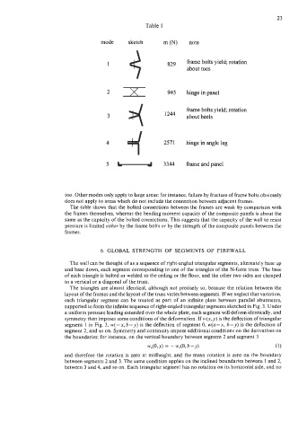
Table 1
mode sketch m o\r> note
3 frame bolts yield; rotation
1 829 about toes
2 >r( 945 hinge in panel
4 frame bolts yield; rotation
3 1244 about heels
4 2571 hinge in angle leg
3344 frame and panel
too. Other modes only apply to large areas: for instance, failure by fracture of frame bolts obviously
does not apply to areas which do not include the connection between adjacent frames.
The table shows that the bolted connections between the frames are weak by comparison with
the frames themselves, whereas the bending moment capacity of the composite panels is about the
same as the capacity of the bolted connections. This suggests that the capacity of the wall to resist
pressure is limited either by the frame bolts or by the strength of the composite panels between the
frames.
6. GLOBAL STRENGTH OF SEGMENTS OF FIREWALL
The wall can be thought of as a sequence of right-angled triangular segments, alternately base up
and base down, each segment corresponding to one of the triangles of the N-form truss. The base
of each triangle is bolted or welded to the ceiling or the floor, and the other two sides are clamped
to a vertical or a diagonal of the truss.
The triangles are almost identical, although not precisely so, because the relation between the
layout of the frames and the layout of the truss varies between segments. If we neglect that variation,
each triangular segment can be treated as part of an infinite plate between parallel abutments,
supported to form the infinite sequence of right-angled triangular segments sketched in Fig. 3. Under
a uniform pressure loading extended over the whole plate, each segment will deform identically, and
symmetry then imposes some conditions of the deformation. If w(x, y) is the deflection of triangular
segment 1 in Fig. 3, w(-x,b-y) is the deflection of segment 0, w(a-x, b-y) is the deflection of
segment 2, and so on. Symmetry and continuity impose additional conditions on the derivatives on
the boundaries: for instance, on the vertical boundary between segment 2 and segment 3
WX(0, y) = - WAO, b - v) (1)
and therefore the rotation is zero at midheight, and the mean rotation is zero on the boundary
between segments 2 and 3. The same condition applies on the inclined boundaries between I and 2,
between 3 and 4, and so on. Each triangular segment has no rotation on its horizontal side, and no