
Page 40 - Failure Analysis Case Studies II
P. 40
26
140 1
0
0 20 I //’ /’ frameboltsyield
0 -LA
0 IO 20 30 40 50
time from start (ms)
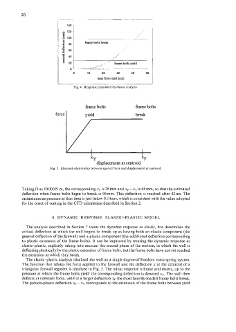
Fig. 4. Response calculated by elastic analysis.
frame bolts frame bolts
force I yield break
, I
xY XF
displacement at centroid
Fig. 5. ldealised relationship between applied force and displacement at centroid.
Taking D as 10 000 N m, the corresponding xy is 28 mm and xF - xy is 68 mm, so that the estimated
deflection when frame bolts begin to break is 96mm. This deflection is reached after 42ms. The
instantaneous pressure at that time is just below 0.1 bars, which is consistent with the value adopted
for the onset of venting in the CFD calculation described in Section 2.
8. DYNAMIC RESPONSE: ELASTIC-PLASTIC MODEL
The analysis described in Section 7 treats the dynamic response as elastic, but determines the
critical deflection at which the wall begins to break up as having both an elastic component (the
general deflection of the firewall) and a plastic component (the additional deflection corresponding
to plastic extension of the frame bolts). It can be improved by treating the dynamic response as
elastic-plastic, explicitly taking into account the second phase of the motion, in which the wall is
deflecting plastically by the plastic extension of frame bolts, but the frame bolts have not yet reached
the extension at which they break.
The elastic-plastic analysis idealised the wall as a single degree-of-freedom mass-spring system.
The function that relates the force applied to the firewall and the deflection x at the centroid of a
triangular firewall segment is idealised in Fig. 5. The initial response is linear and elastic, up to the
pressure at which the frame bolts yield: the corresponding deflection is denoted x,. The wall then
deflects at constant force, until at a larger deflection xF the most heavily-loaded frame bolts break.
The pseudo-plastic deflection xF - xy corresponds to the extension of the frame bolts between yield