
Page 196 - Fair, Geyer, and Okun's Water and wastewater engineering : water supply and wastewater removal
P. 196
JWCL344_ch05_154-193.qxd 8/2/10 9:44 PM Page 158
158 Chapter 5 Water Hydraulics, Transmission, and Appurtenances
aqueducts laid in balanced cut and cover at the ground surface, pressure tunnels dipping be-
neath valleys or hills, and pipelines of fabricated materials following the ground surface, if
necessary over hill and through dale, sometimes even rising above the hydraulic grade line.
Illustrative examples of supply conduits and aqueducts include the following:
1. The Central Arizona aqueduct is a multipurpose water resource project that deliv-
ers Colorado River water into central and southern Arizona (see Fig. 1.6 in Chapter 1).
The aqueduct diversion canal runs about 336 miles (541 km) from Lake Havasu to
a terminus 14 mi (22.5 km) southwest of Tucson. The final extension to Tucson in-
cludes a tunnel through the mountains.
2. The Colorado River aqueduct of the Metropolitan Water District of Southern
California is 242 mi (389 km) long and includes 92 mi (148 km) of grade tunnel,
63 mi (101 km) of canal, 54 mi (86.9 mi) of grade aqueduct, 29 mi (46.7 km) of in-
verted siphons, and 4 mi (6.4 km) of force main.
3. The Delaware aqueduct of New York City comprises 85 miles (137 km) of pressure
tunnel in three sections.
4. Pressure tunnels 25 mi (40.2 km) long supply the metropolitan districts of Boston
and San Francisco.
5. The supply conduits of Springfield, Massachusetts, are made of steel pipe and rein-
forced-concrete pipe; those of Albany, New York, of cast-iron pipe.
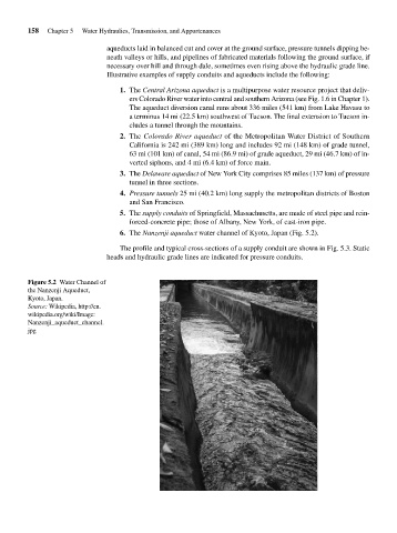
6. The Nanzenji aqueduct water channel of Kyoto, Japan (Fig. 5.2).
The profile and typical cross-sections of a supply conduit are shown in Fig. 5.3. Static
heads and hydraulic grade lines are indicated for pressure conduits.
Figure 5.2 Water Channel of
the Nanzenji Aqueduct,
Kyoto, Japan.
Source: Wikipedia, http://en.
wikipedia.org/wiki/Image:
Nanzenji_aqueduct_channel.
jpg