
Page 197 - Fair, Geyer, and Okun's Water and wastewater engineering : water supply and wastewater removal
P. 197
JWCL344_ch05_154-193.qxd 8/2/10 9:44 PM Page 159
5.2 Fluid Transport 159
Gate
Dam house Construction
Static pressure line
Gate house shafts Static pressure
1 Hydraulic grade line
Canal Distribution or
2 Hydraulic 3
Pressure grade line 3 3 Gate house service reservoir
aqueduct Grade 4
aqueduct Grade Down Static pressure
tunnel
Original surface Profile shaft Up shaft Hydraulic
Original surface
5 grade line
6
Pressure Pipe City
tunnel
1. Lined canal siphon 7
Original Pipe lines
surface
2. Reinforced concrete
pressure aqueduct
Original surface 3. Cut-and-cover
grade aqueduct
4. Grade tunnel
5. pressure tunnel
6. Steel pipe siphon 7. Pipe line
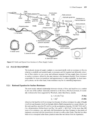
Figure 5.3 Profile and Typical Cross-Sections of a Water Supply Conduit.
5.2 FLUID TRANSPORT
The hydraulic design of supply conduits is concerned chiefly with (a) resistance to flow in
relation to available and needed heads or pressures and (b) required and allowable veloci-
ties of flow relative to cost, scour, and sediment transport. In long supply lines, frictional
or surface resistance offered by the pipe interior is the dominant element. Form resistance
responsible for losses in transitions and appurtenances is often negligible. In short trans-
port systems, on the other hand, form resistance may be of controlling importance.
5.2.1 Rational Equation for Surface Resistance
The most nearly rational relationship between velocity of flow and head loss in a conduit
is also one of the earliest. Generally referred to as the Darcy-Weisbach formula, it is actu-
ally written in the form suggested by Weisbach, rather than Darcy, namely
2
h f f(L>d)(v >2g) (5.10a)
h f KQ 2 (5.10b)
where h f is the head loss in ft (m) (energy loss because of surface resistance) in a pipe of length
L in ft (m) and diameter d in ft (m) through which a fluid is transported at a mean velocity v in
2
2
3
3
ft/s (m/s) and flow rate Q in ft /s (m /s); g is the acceleration of gravity, 32.2 ft/s (9.81 m/s );
5
2
f is a dimensionless friction factor (see Fig. 5.4); and K 8fL> gd . In the more than 100
years of its existence, use, and study, this formulation has been foremost in the minds of
engineers concerned with the transmission of water as well as other fluids. That this has often
been so in a conceptual rather than a practical sense does not detract from its importance.