Page 198 - Fair, Geyer, and Okun's Water and wastewater engineering : water supply and wastewater removal
P. 198

JWCL344_ch05_154-193.qxd  8/2/10  9:44 PM  Page 160


                    160  Chapter 5  Water Hydraulics, Transmission, and Appurtenances

                                                                     VD    VR
                                                                  R
                                                                      V    4  V
                                                   3                4               5               6
                                              6               6               6               6
                                           4    8  10      4    8  10      4    8  10      4    8  10
                                                      2                2               2               2
                                      2                                                                  0.25
                                                                               Rough
                                                              R  f         1     D                       0.15
                                                                             2 log    1.14
                                                              D/k  = 200   f      k
                                      3
                                                                          D/k   20   4R/k                0.10
                                                                                                         0.08
                                      4
                                                                                                         0.06
                                                                              40                     4
                                                                                                         0.05
                                                                                100
                                      5  Laminar                                                         0.04
                                      8gRS  6   f  64                                               6    0.03
                                  V     1     R  f                                 200                          8gRS   V 2
                                                                                      400
                                                                                                         0.025  Dh f /L
                                      8g  7                k (ft)                          1,000         0.020
                                  C                                                                              V 2 /2g
                                     f
                                  1     Boundary material                                2,000           0.018  f
                                            (new)
                                                                                                         0.016
                                         Glass; drawn brass,  “Smooth”
                                      8
                                                                                           4,000     8
                                         copper, lead
                                                                     Smooth
                                                                                                         0.014
                                                                     2 log R  f             10,000
                                         Wrought iron, steel  0.0001 − 0.0003  1
                                                      0.0002 − 0.0006  f      0.8
                                         Asphalted cast iron
                                      9
                                                                                                         0.012
                                                      0.0002 − 0.0008                        20,000
                                         Galvanized iron
                                         Cast iron    0.0004 − 0.002
                                                                                                      7
                                         Wood stave   0.0006 − 0.003
                                                                                                40,000
                                                                                                     10
                                     10
                                                                                                         0.010
                                         Concrete     0.0010 − 0.01                             100,000
                                         Riveted steel  0.0030 − 0.03
                                                                                                         0.009
                                                                                            200,000
                                     11
                                                                                                         0.008
                                        2               3               4               5
                                            2   4  6  8     2   4  6  8     2   4  6  8    2    4  6  8
                                      10              10              10              10
                                                                                                        6
                                                                                                      10
                                                           R  f     D v 3/2   2gh f     8R v 3/2   2gS
                                                                        L
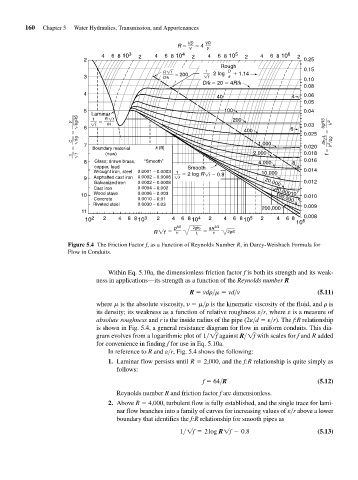
                                 Figure 5.4 The Friction Factor f, as a Function of Reynolds Number R, in Darcy-Weisbach Formula for
                                 Flow in Conduits.
                                             Within Eq. 5.10a, the dimensionless friction factor f is both its strength and its weak-
                                         ness in applications—its strength as a function of the Reynolds number R
                                                                      R   vd >    vd>v                       (5.11)
                                         where   is the absolute viscosity,      >  is the kinematic viscosity of the fluid, and   is
                                         its density; its weakness as a function of relative roughness e>r, where e is a measure of
                                         absolute roughness and r is the inside radius of the pipe (2e>d   e>r). The f:R relationship
                                         is shown in Fig. 5.4, a general resistance diagram for flow in uniform conduits. This dia-
                                         gram evolves from a logarithmic plot of 1> 1f  against R>1f  with scales for f and R added
                                         for convenience in finding f for use in Eq. 5.10a.
                                             In reference to R and e>r, Fig. 5.4 shows the following:
                                             1. Laminar flow persists until R   2,000, and the f:R relationship is quite simply as
                                                follows:
                                                                          f   64>R                           (5.12)
                                                Reynolds number R and friction factor f are dimensionless.
                                             2. Above R   4,000, turbulent flow is fully established, and the single trace for lami-
                                                nar flow branches into a family of curves for increasing values of e>r above a lower
                                                boundary that identifies the f:R relationship for smooth pipes as
                                                                   1>1f = 2 log R1f - 0.8                    (5.13)
   193   194   195   196   197   198   199   200   201   202   203