
Page 225 - Fair, Geyer, and Okun's Water and wastewater engineering : water supply and wastewater removal
P. 225
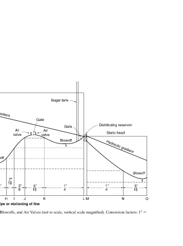
JWCL344_ch05_154-193.qxd  8/2/10  9:44 PM  Page 186


                                                                                                                       O
                                                                                                        Blowoff  5"  16


                                                                            Distributing reservoir  Static head  Hydraulic gradient  1"  4  N


                                                                                                                       M
                                                                                                                       L


                                                             Sugar tank      Gate    Blowoff                    1"  4


                                                                               Air  valve                              K
                                                                         Gate
                                                                                                                5"  16


                                                                                                                       J

                                                                               Air  valve                       3"  8  I       Profile of Pipeline Showing Pipe Thickness and Location of Gates, Blowoffs, and Air Valves (not to scale, vertical scale magnified). Conversion factors: 1
                                                                                                            7"  16     H  Length of pipe or stationing of line


                                                       Static head  Hydraulic gradient         Blowoff      7"  3"  16  8  1"  2  G  F


                                                                     Air  valve                             5"  16     E  D

                                                              Gate                                              1"  4


                                                                    Air  valve                              Thickness of pipe  C


                                                                              Blowoff                           5"  16            0.3048 m.


                                                   Intake reservoir  Gate                                       1"  4  B          1 ft


                                                                                                                       A
                                                                            1"  4  5"  16  3"  8  7"  16  1"  2                   25.4 mm; 1

                                                                                                                               Figure 5.12  1 in.
                                                                                                         Allowable head for given thickness


                                                                                             Elevation, ft


           186