
Page 229 - Fair, Geyer, and Okun's Water and wastewater engineering : water supply and wastewater removal
P. 229
JWCL344_ch05_154-193.qxd 8/2/10 9:44 PM Page 190
190 Chapter 5 Water Hydraulics, Transmission, and Appurtenances
5.9.14 Other Appurtenances
Other appurtenances that may be necessary include the following:
1. Surge tanks at the end of the line to reduce water hammer created by operation of a
valve at the end of the line
2. Pressure relief valves or overflow towers on one or more summits to keep the pres-
sure in the line below a given value by letting water discharge to waste when the
pressure builds up beyond the design value
3. Self-acting shutoff valves triggered to close when the pipe velocity exceeds a pre-
determined value as a result of an accident
4. Altitude-control valves that shut off the inlet to service reservoirs, elevated tanks,
and standpipes before overflow levels are reached
5. Venturi or other meters and recorders to measure the flows.
PROBLEMS/QUESTIONS
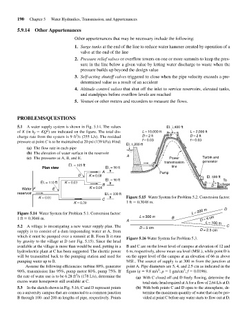
5.1 A water supply system is shown in Fig. 5.14. The values EI. 1,400 ft
2
of K (in h f KQ ) are indicated on the figure. The total dis- L = 10,000 ft L = 2,000 ft
3
charge rate from the system is 9 ft /s (255 L/s). The residual D = 2 ft B D = 2 ft
pressure at point C is to be maintained at 20 psi (139 kPa). Find: f = 0.03 f = 0.03
EI. 1,200 ft
(a) The flow rate in each pipe
(b) The elevation of water surface in the reservoir
(c) The pressures at A, B, and E. A Power Turbin and
generator
transmission
EI. = 105 ft P
Plan view EI. = 90 ft line
A
D K = 0.08 Pump
EI. = 90 ft C EI. 800 ft
EI. = 110 ft K = 0.03 To
B D village
Water F E K = 0.08
reservoir EI. = 100 ft
K = 0.01 C Figure 5.15 Water System for Problem 5.2. Conversion factor:
K = 0.20 1 ft 0.3048 m.
L = 200 m D
Figure 5.14 Water System for Problem 5.1. Conversion factor:
L = 300 m
1 ft 0.3048 m. B D = 4 cm
A
L = 100 m
5.2 A village is investigating a new water supply plan. The D = 5 cm C
supply is to consist of a dam impounding water at A, from D = 2.5 cm
which it must be pumped over a summit at B. From B it runs Figure 5.16 Water System for Problem 5.3.
by gravity to the village at D (see Fig. 5.15). Since the head
available at the village is more than would be used, putting in a B and C are on the lower level of campus at elevation of 12 and
hydroelectric plant at C has been suggested. The electric power 6 m, respectively, above mean sea level (MSL), while point D is
will be transmitted back to the pumping station and used for on the upper level of the campus at an elevation of 66 m above
pumping water up to B. MSL. The source of supply is at 300 m from the junction at
Assume the following efficiencies: turbine 80%, generator point A. Pipe diameters are 5, 4, and 2.5 cm as indicated in the
2
3
90%, transmission line 95%, pump motor 80%, pump 75%. If figure (g 9.8 m/s ; 1 gm/cm ; f 0.0196).
3
the rate of water use is to be 6.28 ft /s (178 L/s), determine the (a) With C closed off and D freely flowing, determine the
excess water horsepower still available at C. total static head required at A for a flow of 2.64 L/s at D.
5.3 In the sketch shown in Fig. 5.16, C and D represent points (b) With both points C and D open to the atmosphere, de-
on a university campus that are connected to a common junction termine the maximum quantity of water that can be pro-
B through 100- and 200-m lengths of pipe, respectively. Points vided at point C before any water starts to flow out at D.