Page 231 - Fair, Geyer, and Okun's Water and wastewater engineering : water supply and wastewater removal
P. 231

JWCL344_ch05_154-193.qxd  8/2/10  9:44 PM  Page 192


                    192  Chapter 5  Water Hydraulics, Transmission, and Appurtenances
                    The measured residual pressures are as follows:  The head delivered by the pumps to the water is 100 ft. The
                        Point B   300 kPa                           value of C for all pipes is 100. Assume the following elevations:
                        Point C   500 kPa                                  A 900.00 ft
                    The known flows are as follows:                        B  9l5.00 ft
                                                                           C 910.00 ft
                        Pipe BD   30 L/s
                        Pipe BE   75 L/s                                (a) Determine the required diameter of main PA, if the
                                                                           pressure at point A is not allowed to drop below 52 psi.
                    C for all pipes   100.
                                                                        (b) Determine the required diameter of pipe BC, if the
                        (a) Calculate the flow in line BC.                 maximum allowed head loss in the network ABC is
                        (b) Find the residual pressure at point D.         3 ft/1,000 ft.
                        (c) Compute the maximum water level in reservoir E.  (c) Calculate the actual residual pressures at points A, B,
                        (d) Determine the required diameter for pipe AB.
                                                                           and C.
                    5.9  A water supply system consists of a ground reservoir with  5.11 Water is pumped from ground reservoir A to the elevated
                    lift pumps (A), elevated storage (C), a withdrawal point (B),  reservoir G through the network of pipes shown in Fig. 5.22.
                    and equivalent pipelines as given in the plan view in Fig. 5.20.
                    Assume the following elevations:                The following data are given:
                                                                        All pipes have the same diameter   300 mm
                        Water level in ground reservoir (A)    600.00 m  C for all pipes   100
                        Ground level at withdrawal point (B)    609.10 m  Water level in ground reservoir   500 m
                        Ground level at elevated water tank (C)   612.20 m
                                                                        Water flow rate   80 L/s
                        The lift pumps provide flow at a discharge pressure of 550  Pump operating head   70 m.
                    kPa. The value of C for all pipes is 100.
                                                                        (a) Calculate the maximum water level in the elevated
                        Compute the discharge, Q, in L/s at withdrawal point B for  reservoir when valves E and F are closed.
                    the following conditions:                           (b) How many meters will the water level rise in the ele-
                        (a) If the residual pressure at point B is 200 kPa  vated reservoir if valves E and F were opened?
                        (b) If water is neither flowing to, nor from, the elevated           C
                           storage tank.
                                                                                  L = 1,000 m   L = 1,000 m
                                                                       A               B                      G
                                          B                  C       Ground  L = 1,600 m          D L = 1,200 m
                                                           Elevated  reservoir  P
                             d = 300 mm       d = 250 mm    tank               L = 500 m           L = 500 m Elevated
                        P    L = 1,500 m      L = 900 m
                                          Q                                           E L = 1,000 m  F     reservoir
                                         Water
                        A              withdrawal                   Figure 5.22 Water System for Problem 5.11.
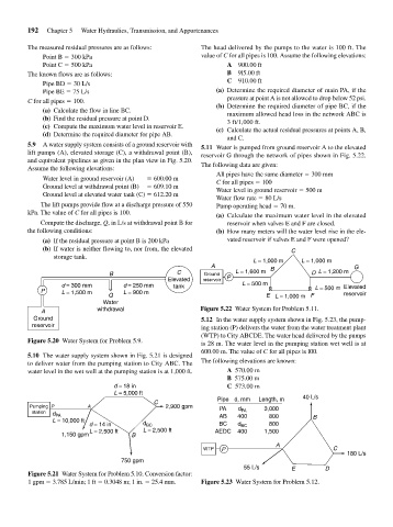
                      Ground                                        5.12 In the water supply system shown in Fig. 5.23, the pump-
                     reservoir                                      ing station (P) delivers the water from the water treatment plant
                                                                    (WTP) to City ABCDE. The water head delivered by the pumps
                    Figure 5.20 Water System for Problem 5.9.       is 28 m. The water level in the pumping station wet well is at
                                                                    600.00 m. The value of C for all pipes is l00.
                    5.10 The water supply system shown in Fig. 5.21 is designed
                    to deliver water from the pumping station to City ABC. The  The following elevations are known:
                    water level in the wet well at the pumping station is at 1,000 ft.  A 570.00 m
                                                                           B 575.00 m
                                            d = 18 in                      C 573.00 m
                                            L = 5,000 ft
                                                                        Pipe d, mm  Length, m   40 L/s
                                                       C
                    Pumping P       A                     2,900 gpm      PA          3,000
                     station                                                  d PA
                           d PA                                          AB   400      800         B
                           L = 10,000 ft
                                     d = 14 in      d BC                 BC   d BC     800
                                     L = 2,500 ft   L = 2,500 ft        AEDC  400    1,500
                             1,150 gpm           B
                                                                                         A
                                                                     WTP  P                             C
                                                                                                            180 L/s
                                              750 gpm
                                                                                55 L/s       E        D
                    Figure 5.21 Water System for Problem 5.10. Conversion factor:
                    1 gpm   3.785 L/min; 1 ft   0.3048 m; 1 in.   25.4 mm.  Figure 5.23 Water System for Problem 5.12.
   226   227   228   229   230   231   232   233   234   235   236