
Page 226 - Fair, Geyer, and Okun's Water and wastewater engineering : water supply and wastewater removal
P. 226
JWCL344_ch05_154-193.qxd 8/2/10 9:44 PM Page 187
5.9 Appurtenances 187
L c
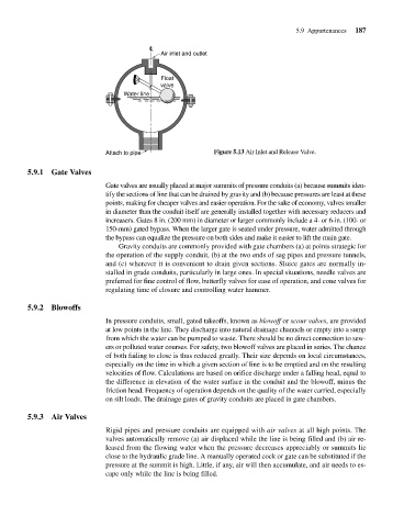
Air inlet and outlet
Float
valve
Water line
Attach to pipe Figure 5.13 Air Inlet and Release Valve.
5.9.1 Gate Valves
Gate valves are usually placed at major summits of pressure conduits (a) because summits iden-
tify the sections of line that can be drained by gravity and (b) because pressures are least at these
points, making for cheaper valves and easier operation. For the sake of economy, valves smaller
in diameter than the conduit itself are generally installed together with necessary reducers and
increasers. Gates 8 in. (200 mm) in diameter or larger commonly include a 4- or 6-in. (100- or
150-mm) gated bypass. When the larger gate is seated under pressure, water admitted through
the bypass can equalize the pressure on both sides and make it easier to lift the main gate.
Gravity conduits are commonly provided with gate chambers (a) at points strategic for
the operation of the supply conduit, (b) at the two ends of sag pipes and pressure tunnels,
and (c) wherever it is convenient to drain given sections. Sluice gates are normally in-
stalled in grade conduits, particularly in large ones. In special situations, needle valves are
preferred for fine control of flow, butterfly valves for ease of operation, and cone valves for
regulating time of closure and controlling water hammer.
5.9.2 Blowoffs
In pressure conduits, small, gated takeoffs, known as blowoff or scour valves, are provided
at low points in the line. They discharge into natural drainage channels or empty into a sump
from which the water can be pumped to waste. There should be no direct connection to sew-
ers or polluted water courses. For safety, two blowoff valves are placed in series. The chance
of both failing to close is thus reduced greatly. Their size depends on local circumstances,
especially on the time in which a given section of line is to be emptied and on the resulting
velocities of flow. Calculations are based on orifice discharge under a falling head, equal to
the difference in elevation of the water surface in the conduit and the blowoff, minus the
friction head. Frequency of operation depends on the quality of the water carried, especially
on silt loads. The drainage gates of gravity conduits are placed in gate chambers.
5.9.3 Air Valves
Rigid pipes and pressure conduits are equipped with air valves at all high points. The
valves automatically remove (a) air displaced while the line is being filled and (b) air re-
leased from the flowing water when the pressure decreases appreciably or summits lie
close to the hydraulic grade line. A manually operated cock or gate can be substituted if the
pressure at the summit is high. Little, if any, air will then accumulate, and air needs to es-
cape only while the line is being filled.