
Page 241 - Fair, Geyer, and Okun's Water and wastewater engineering : water supply and wastewater removal
P. 241
JWCL344_ch06_194-229.qxd 8/2/10 9:51 PM Page 202
202 Chapter 6 Water Distribution Systems: Components, Design, and Operation
6.5 FIELD PERFORMANCE OF EXISTING SYSTEMS
The hydraulic performance of existing distribution systems is determined most directly
and expeditiously by pressure surveys and hydrant-flow tests. Such tests should cover all
typical portions of the community: the high-value district, residential neighborhoods and
industrial areas of different kinds, the outskirts, and high-service zones. If need be, tests
can be extended into every block. The results will establish available pressures and flows
and existing deficiencies. These can then be made the basis of hydraulic calculations for
extensions, reinforcements, and new gridiron layouts. Follow-up tests can show how suc-
cessful the desired changes have been.
Pressure surveys yield the most rudimentary information about networks; if they are
conducted both at night (minimum flow) and during the day (normal demand), they will
indicate the hydraulic efficiency of the system in meeting common requirements.
However, they will not establish the probable behavior of the system under stress, for ex-
ample, during a serious conflagration.
Hydrant-flow tests commonly include (a) observation of the pressure at a centrally
situated hydrant during the conduct of the test and (b) measurement of the combined
flow from a group of neighboring hydrants. Velocity heads in the jets issuing from the
hydrants are usually measured by hydrant pitot tubes. If the tests are to be significant,
(a) the hydrants tested should form a group such as might be called into play in fight-
ing a serious fire in the district under study, (b) water should be drawn at a rate that
will drop the pressure enough to keep it from being measurably affected by normal
fluctuations in draft within the system, and (c) the time of test should coincide with
drafts (domestic, industrial, and the like) in the remainder of the system, reasonably
close to coincident values.
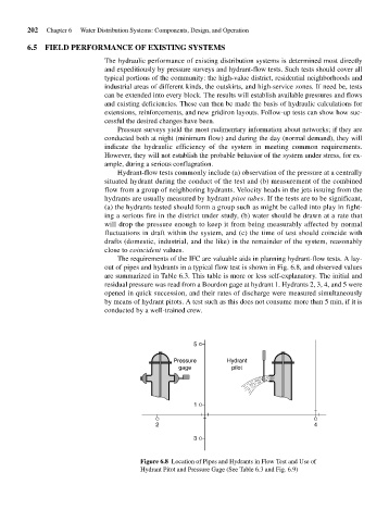
The requirements of the IFC are valuable aids in planning hydrant-flow tests. A lay-
out of pipes and hydrants in a typical flow test is shown in Fig. 6.8, and observed values
are summarized in Table 6.3. This table is more or less self-explanatory. The initial and
residual pressure was read from a Bourdon gage at hydrant 1. Hydrants 2, 3, 4, and 5 were
opened in quick succession, and their rates of discharge were measured simultaneously
by means of hydrant pitots. A test such as this does not consume more than 5 min, if it is
conducted by a well-trained crew.
5
Pressure Hydrant
gage pilot
1
2 4
3
Figure 6.8 Location of Pipes and Hydrants in Flow Test and Use of
Hydrant Pitot and Pressure Gage (See Table 6.3 and Fig. 6.9)