Page 258 - Fair, Geyer, and Okun's Water and wastewater engineering : water supply and wastewater removal
P. 258

JWCL344_ch06_194-229.qxd  8/2/10  9:51 PM  Page 218


                    218  Chapter 6  Water Distribution Systems: Components, Design, and Operation
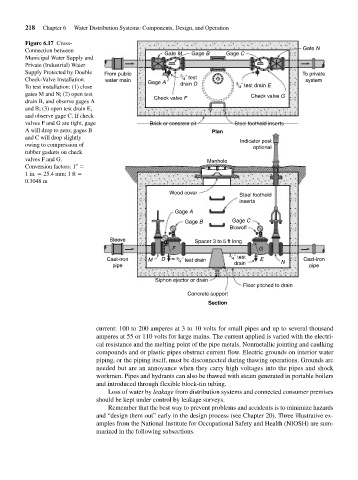
                    Figure 6.17 Cross-
                    Connection between                        Gate M  Gage B     Gage C                 Gate N
                    Municipal Water Supply and
                    Private (Industrial) Water
                    Supply Protected by Double  From public        3                                    To private
                    Check-Valve Installation.  water main  Gage A   	 4 ˝ test                           system
                    To test installation: (1) close                drain D          3 	 4 ˝ test drain E
                    gates M and N; (2) open test                                        Check valve G
                    drain B, and observe gages A           Check valve F
                    and B; (3) open test drain E,
                    and observe gage C. If check
                    valves F and G are tight, gage        Brick or concrete pit    Steel foothold inserts
                    A will drop to zero; gages B                             Plan
                    and C will drop slightly                                         Indicator post
                    owing to compression of
                                                                                         optional
                    rubber gaskets on check
                    valves F and G.                                        Manhole
                    Conversion factors: 1
                    1 in.   25.4 mm; 1 ft
                    0.3048 m
                                                                Wood cover
                                                                                     Steel foothold
                                                                                     inserts
                                                                 Gage A
                                                                    Gage B         Gage C
                                                                                  Blowoff
                                              Sleeve                   Spacer 3 to 5 ft long
                                                                F                          G
                                                                                  3
                                             Cast-iron   M   D    3 	 4 ˝ test drain  	 4 ˝ test  E  N  Cast-iron
                                              pipe                                 drain                  pipe

                                                           Siphon ejector or drain
                                                                                      Floor pitched to drain
                                                                     Concrete support
                                                                           Section


                                         current: 100 to 200 amperes at 3 to 10 volts for small pipes and up to several thousand
                                         amperes at 55 or 110 volts for large mains. The current applied is varied with the electri-
                                         cal resistance and the melting point of the pipe metals. Nonmetallic jointing and caulking
                                         compounds and or plastic pipes obstruct current flow. Electric grounds on interior water
                                         piping, or the piping itself, must be disconnected during thawing operations. Grounds are
                                         needed but are an annoyance when they carry high voltages into the pipes and shock
                                         workmen. Pipes and hydrants can also be thawed with steam generated in portable boilers
                                         and introduced through flexible block-tin tubing.
                                             Loss of water by leakage from distribution systems and connected consumer premises
                                         should be kept under control by leakage surveys.
                                             Remember that the best way to prevent problems and accidents is to minimize hazards
                                         and “design them out” early in the design process (see Chapter 20). Three illustrative ex-
                                         amples from the National Institute for Occupational Safety and Health (NIOSH) are sum-
                                         marized in the following subsections.
   253   254   255   256   257   258   259   260   261   262   263