Page 253 - Fair, Geyer, and Okun's Water and wastewater engineering : water supply and wastewater removal
P. 253

JWCL344_ch06_194-229.qxd  8/2/10  9:51 PM  Page 213


                                                                                  6.6 Office Studies of Pipe Networks  213
                    6.6.3  Pipe Equivalence

                                         In this method, a complex system of pipes is replaced by a single hydraulically equiv-
                                         alent line. The method cannot be applied directly to pipe systems containing
                                         crossovers or takeoffs. However, it is frequently possible, by judicious skeletonizing
                                         of the network, to obtain significant information on the quantity and pressure of water
                                         available at important points, or to reduce the number of circuits to be considered. In
                                         paring the system down to a workable frame, the analyst can be guided by the fact that
                                         pipes contribute little to flow (a) when they are small (6 in. (150mm) and under in
                                         most systems and 8 or 10 in. (200 or 250 mm) in large systems) and (b) when they are
                                         at right angles to the general direction of flow and there is no appreciable pressure dif-
                                         ferential between their junctions in the system.
                                             Pipe equivalence makes use of the two hydraulic axioms:
                                             1. Head losses through pipes in series, such as AB and BD in Fig. 6.14, are additive:


                                                                      H AD   H AB   H BD
                                                                      Q AB   Q BD
                                                                      H AD   H AC   H CD
                                                                      Q AC   Q CD

                                             2. Flows through pipes in parallel, such as ABD and ACD in Fig. 6.14, must be so dis-
                                                tributed that the head losses are identical:


                                                                      H ABD   H ACD


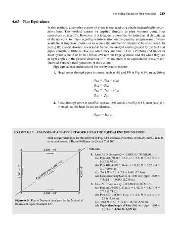
                     EXAMPLE 6.5   ANALYSIS OF A WATER NETWORK USING THE EQUIVALENT PIPE METHOD
                                         Find an equivalent pipe for the network of Fig. 6.14. Express Q in MGD or MLD; s in ‰; H in ft
                                          or m; and assume a Hazen-Williams coefficient C of 100.

                         B             4,000´ 16˝           D      Solution:
                                                                    1. Line ABD. Assume Q   1 MGD (3.785 MLD).
                                                                       (a) Pipe AB, 3000 ft, 12 in.; s   2.1; H   2.1   3
                                                                          6.3 ft (1.92 m).
                         3,000´ 12˝  Equivalent pipe 5,000´ 14˝  3,000´ 8˝  (b) Pipe BD, 4,000 ft, 16 in.; s   0.52; H   0.52   4
                                                                          2.1 ft (0.64 m).
                                                                       (c) Total H   6.3   2.1   8.4 ft (2.5 6m).
                                                                       (d) Equivalent length of 12-in. (300 mm) pipe: 1,000
                                                                          8.4 2.1   4,000 ft (1,219 m).
                                                                    2. Line ACD. Assume Q   0.5 MGD (1.89 MLD).
                                                                       (a) Pipe AC, 4,000 ft, l0 in.; s   1.42; H   1.42   4
                                                                          5.7 ft (1.74 m).
                         A             4,000´ 10˝           C
                                                                       (b) Pipe CD, 3,000 ft, 8 in.; s   4.2; H   4.2   3
                                                                          12.6 ft (3.84 m).
                      Figure 6.14 Plan of Network Analyzed by the Method of
                                                                       (c) Total H   5.7   12.6   18.3 ft (5.58 m).
                      Equivalent Pipes (Example 6.5)
                                                                       (d) Equivalent length of 8-in. (200 mm) pipe: 1,000
                                                                          18.3 4.2   4,360 ft (1,329 m).
   248   249   250   251   252   253   254   255   256   257   258