
Page 250 - Fair, Geyer, and Okun's Water and wastewater engineering : water supply and wastewater removal
P. 250
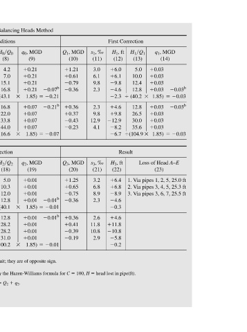
JWCL344_ch06_194-229.qxd  8/2/10  9:51 PM  Page 210


                                          0.03 b    0.03   0.03 b    0.03
                         q 1 , MGD   (14)   0.03   0.03   0.03   0.03  1.85)   0.03   0.03   0.03   0.03  1.85)  Loss of Head A–E  (23)  1. Via pipes 1, 2, 5, 25.0 ft 2. Via pipes 3, 4, 5, 25.3 ft 3. Via pipes 3, 6, 7, 25.5 ft


                                                 12.8  26.5  30.0  35.6
                         H 1  Q 1
                    First Correction  H 1 , ft   (12)   6.0   6.1   9.8   4.6  (40.2      2.3   4.6   9.8   12.9   8.2   (104.9   6.7  Result  H 3 , ft   (22)   6.4   6.8   8.9   4.6   0.3   4.6   11.8   10.8   5.8   0.2  head lost in pipe(ft).
                            (13)
                                5.0
                                   10.0
                                         12.8
                                      12.4


                         s 1 , ‰   (11)  3.0  6.1  9.8  2.3  2.3  9.8  12.9  4.1  s 3 , ‰   (21)  3.2  6.8  8.9  2.3  2.6  11.8  10.8  2.9


                         Q 1 , MGD   (10)   1.21   0.61   0.79   0.36   0.36   0.37   0.43   0.23  Q 3 , MGD   (20)   1.25   0.65   0.75   0.36   0.36   0.41   0.39   0.19  100, H


                                          0.07 b    0.21   0.21 b    0.07                  0.01 b    0.01   0.01 b    0.01
               Analysis of the Network of Figure 6.12 (Example 6.3) Using the Balancing Heads Method

                         q 0 , MGD   (9)   0.21   0.21   0.21   0.21  1.85)   0.07   0.07   0.07   0.07  1.85)  q 2 , MGD   (19)   0.01   0.01   0.01   0.01  1.85)   0.01   0.01   0.01   0.01  1.85)


                                                 16.8  22.0  33.8  44.0     H 2  Q 2  (18)  5.0  10.3  12.0  12.8     12.8  28.2  28.2  31.0     q 2 .     Q 2
                    Assumed Conditions  H 0 , ft  (7)   4.2   2.8   15.1   8.4  (43.1      16.5   8.4   6.6   16.9   13.2  (116.6      15.1  Second Correction  H 2 , ft   (17)   6.2   6.6   9.1   4.6  (40.1      0.9   4.6   11.3   11.3   6.2  (100.2      1.6     q 1 ; Q 3
                         H 0  Q 0
                                   7.0
                                      15.1
                                         16.8
                                4.2
                            (8)


                         s 0 , ‰   (6)  2.1  2.8  15.1  4.2  4.2  6.6  16.9  6.6  s 2 , ‰   (16)  3.1  6.6  9.1  2.3  2.3  11.3  11.3  3.1  slope of hydraulic gradient or friction loss in ft per 1,000 (‰) by the Hazen-Williams formula for C  Q 1     q 0 ; Q 2  3.785 MLD.


                         Q 0, MGD  (5)   1.0   0.4   1.0   0.5   0.5   0.3   0.5   0.3  Q 2, MGD   (15)   1.24   0.64   0.76   0.36   0.36   0.40   0.40   0.20 b Corrections in this column are those calculated for the same pipe in the companion circuit; they are of opposite sign.     Q 0     Q 1  25.4 mm; 1 MGD


                         Diameter, in.  (4)  12  8  8  8  8  6  6  6     Diameter, in.  (4)  12  8  8  8  8  6  6  6        gH  =- 1.85g(H>Q) ,  0.3048 m; 1 in.


                         Length, ft  (3)  2,000  1,000  1,000  2,000  2,000  1,000  1,000  2,000  Length, ft  (3)  2,000  1,000  1,000  2,000  2,000  1,000  1,000  2,000 a Pipe serves more than one circuit; first consideration of this pipe.


                    Network                                         Network

                         Pipe No.  (2)  1  2  3  4 a  4 c  5  6  7       Pipe No.  (2)  1  2  3  4 a  4 c  5  6  7    c Second consideration of this pipe.  flow in MGD; s  flow correction in MGD;  q  Conversion factors: 1 ft


               Table 6.4  Circuit No.  (1)  I    II                      Circuit No.  (1)  I     II                          Q     q


           210