Page 252 - Fair, Geyer, and Okun's Water and wastewater engineering : water supply and wastewater removal
P. 252

JWCL344_ch06_194-229.qxd  8/2/10  9:51 PM  Page 212


                    212  Chapter 6  Water Distribution Systems: Components, Design, and Operation


                                                                                           Elevation of
                                                                                  Take-off  F  water table
                                                                                            E   50´
                                                                   H 1                           50.0´  H 0
                                                              H 0  106´
                                                              110´  1,800´ 10˝ 100  H          900´ 10˝ 100  69.2´  H 1
                                                                             H
                                                                               0
                                                                                   1
                                                                                                         0
                                         E    160´                           60.0´ 36.8´                E    100´
                                          0
                                                                                                         1
                                         E    156´  D                      2,200´ 8˝ 100           E    E    119.2´
                                          1
                                                H 1  44.0´  600´ 10˝ 120                        1,000´ 10˝ 120  50.0´  H 0
                                                H 0  40.0´      H 0  H 1                            51.9´  H 1
                                                 C             50.0´ 28.9´
                                                   Elevation of  1,800´ 6˝ 100        B    30.0´ H 0
                                             Inflow  water table                E 0 1    150´  8.9´  H 1  Elevation of
                                                    E   200´
                                                                                E    171.1´
                                                                                                 A  water table
                                                                                                    E   180´
                                                                                         500´ 12˝ 120
                                                                                                  Inflow
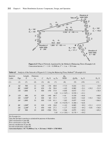
                                         Figure 6.13 Plan of Network Aanalyzed by the Method of Balancing Flows (Example 6.4)
                                         Conversion factors: 1   1 ft   0.3048 m; 1   1 in.   25.4 mm


                     Table 6.5  Analysis of the Network of Figure 6.13. Using the Balancing Flows Method a,b  (Example 6.4)
                     Junction      Length,  Diameter,                      Q 0 ,
                     Letter   Pipe    ft      in.     C   H 0 , ft  s 0 , ‰  MGD    Q 0 /H 0  h 0 , ft     H 1 , ft
                     (1)      (2)    (3)      (4)    (5)   (6)    (7)      (8)       (9)     (10)          (11)

                     B        AB     500      12     120   + 30  60.0     + 7.33   0.244    - 21.1          + 8.9
                              BE    1,000 c   10     120   - 50  50.0     - 4.12   0.082    - 21.1  + 19.2  - 51.9
                              CB    1,800      6     100   + 50  27.8     + 0.66   0.013    - 21.1         + 28.9
                                                                  1.85  *  ( 3.87) ,  0.339 =  + 21.1
                                                                          +
                     D        CD     600      10     120   + 40  66.7     + 4.8    0.120    + 4.01         + 44.0
                              DE    2,200 d    8     100   - 60  27.3     - 1.37   0.023    + 4.01  + 19.2  - 36.8
                              DF    1,800     10     100   - 110  61.1    - 3.82   0.037    + 4.01        - 106.0
                                                                  1.85  *  ( 0.39) ,  0.180 =  - 4.01
                                                                          -
                     E        BE    1,000 e   10     120   + 50  50.0     + 4.12   0.082    - 19.2  + 21.1  + 51.9
                              DE    2,200 f    8     100   + 60  27.3     + 1.37   0.023    - 19.2  - 4.01  + 36.8
                              EF     900      10     100   - 500  55.6    - 3.64   0.073    - 19.2         - 69.2
                                                                  1.85  *  ( 1.85) ,  0.178 =  + 19.2
                                                                          +
                     a
                      For Example 6.4.
                     b
                      Only the first head correction is calculated for purposes of illustration.
                     c
                      First consideration of pipe BE.
                     d
                      First consideration of pipe DE.
                     e
                      Second consideration of pipe BE.
                     f
                     Second consideration of pipe DE.
                     Conversion factors: 1 ft   0.3048 m; 1 in.   25.4 mm; 1 MGD   3.785 MLD.
   247   248   249   250   251   252   253   254   255   256   257