
Page 249 - Fair, Geyer, and Okun's Water and wastewater engineering : water supply and wastewater removal
P. 249
JWCL344_ch06_194-229.qxd 8/2/10 9:51 PM Page 210
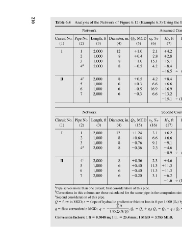
Analysis of the Network of Figure 6.12 (Example 6.3) Using the Balancing Heads Method
Assumed Conditions First Correction q 1 , MGD H 1 Q 1 H 1 , ft s 1 , ‰ Q 1 , MGD q 0 , MGD H 0 Q 0 H 0 , ft (14) (13) (12) (11) (10) (9) (8) (7) 0.03 5.0 6.0 3.0 1.21 0.21 4.2 4.2 0.03 10.0 6.1 6.1 0.61 0.21 7.0 2.8 0.03 12.4 9.8 9.8 0.79 0.21 15.1 15.1 0.03 b 0.03 12.8 4.6 2.3 0.36 0.07 b 0.21 16.8 8.4 0.03 1.85) (40.2 2.3 0.21 1.85) (43.1 16.5 0.03 b 0.03 12.8 4.6 2.3 0.36 0.21 b 0.07 16.8 8.4 0.03 26.5 9.8 9.8 0.37 0.07 22.0
s 0 , ‰ (6) 2.1 2.8 15.1 4.2 4.2 6.6 16.9 6.6 s 2 , ‰ (16) 3.1 6.6 9.1 2.3 2.3 11.3 11.3 3.1 slope of hydraulic gradient or friction loss in ft per 1,000 (‰) by the Hazen-Williams formula for C Q 1 q 0 ; Q 2 3.785 MLD.
Q 0 , MGD (5) 1.0 0.4 1.0 0.5 0.5 0.3 0.5 0.3 Q 2 , MGD (15) 1.24 0.64 0.76 0.36 0.36 0.40 0.40 0.20 b Corrections in this column are those calculated for the same pipe in the companion circuit; they are of opposite sign. Q 0 Q 1 25.4 mm; 1 MGD
Diameter, in. (4) 12 8 8 8 8 6 6 6 Diameter, in. (4) 12 8 8 8 8 6 6 6 gH =- 1.85g(H>Q) , 0.3048 m; 1 in.
Length, ft (3) 2,000 1,000 1,000 2,000 2,000 1,000 1,000 2,000 Length, ft (3) 2,000 1,000 1,000 2,000 2,000 1,000 1,000 2,000 a Pipe serves more than one circuit; first consideration of this pipe.
Network Network
Pipe No. (2) 1 2 3 4 a 4 c 5 6 7 Pipe No. (2) 1 2 3 4 a 4 c 5 6 7 c Second consideration of this pipe. flow in MGD; s flow correction in MGD; q Conversion factors: 1 ft
Table 6.4 Circuit No. (1) I II Circuit No. (1) I II Q q
210