
Page 248 - Fair, Geyer, and Okun's Water and wastewater engineering : water supply and wastewater removal
P. 248
JWCL344_ch06_194-229.qxd 8/2/10 9:51 PM Page 209
6.6 Office Studies of Pipe Networks 209
Although the network in Example 6.3 is simple, it cannot be solved conveniently by
algebraic methods, because it contains two interfering hydraulic constituents: (a) a crossover
(pipe 4) involved in more than one circuit and (b) a series of takeoffs representing water used
along the pipelines, fire flows through hydrants, or supplies through to neighboring circuits.
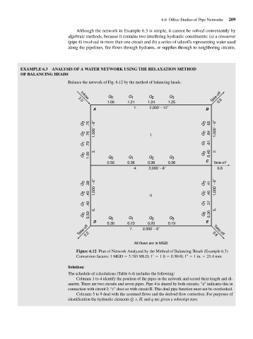
EXAMPLE 6.3 ANALYSIS OF A WATER NETWORK USING THE RELAXATION METHOD
OF BALANCING HEADS
Balance the network of Fig. 6.12 by the method of balancing heads.
Q 0 Q 1 Q 2 Q 3 Take-off
Inflow
2.0
1.00 1.21 1.24 1.25 0.6
A 1. 2,000´ 12˝ B
Q 3 .75 1,000´ 8˝ Q 3 .65 1,000´ 8˝
Q 2 .76 I Q 2 .64
Q 1 .79 Q 1 .61
3. 2.
Q 0 1.00 Q 0 Q 1 Q 2 Q 3 Q 0 0.40
0.50 0.36 0.36 0.36 C Take-off
4. 2,000´ 8˝ 0.6
Q 3 .39 1,000´ 6˝ Q 3 .41 1,000´ 6˝
Q 2 .40 II Q 2 .40
Q 1 .43 Q 1 .37
6. 5.
Q 0 0.50 Q Q Q Q Q 0 0.30
2
1
3
0
D 0.30 0.23 0.20 0.19 E
Take-off 0.2 7. 2,000´ 6˝ 0.6
Take-off
All flows are in MGD
Figure 6.12 Plan of Network Analyzed by the Method of Balancing Heads (Example 6.3)
Conversion factors: 1 MGD 3.785 MLD; 1 1 ft 0.3048; 1 1 in. 25.4 mm
Solution:
The schedule of calculations (Table 6.4) includes the following:
Columns 1 to 4 identify the position of the pipes in the network and record their length and di-
ameter. There are two circuits and seven pipes. Pipe 4 is shared by both circuits; “a” indicates this in
connection with circuit I; “c” does so with circuit II. This dual pipe function must not be overlooked.
Columns 5 to 9 deal with the assumed flows and the derived flow correction. For purposes of
identification the hydraulic elements Q, s, H, and q are given a subscript zero.