Page 247 - Fair, Geyer, and Okun's Water and wastewater engineering : water supply and wastewater removal
P. 247

JWCL344_ch06_194-229.qxd  8/2/10  9:51 PM  Page 208


                    208  Chapter 6  Water Distribution Systems: Components, Design, and Operation
                                                                                   Take-off
                    Q i            Q 1                 Q i            Q 1            T
                                                         Inflow
                     Inflow
                              Assumed flow Q i
                               incorrect by  q

                                                                                    Q 3

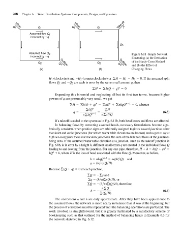
                              Assumed flow Q 2                                             Figure 6.11 Simple Network
                               incorrect by  q
                                                                                           Illustrating (a) the Derivation
                                                                                           of the Hardy-Cross Method
                                   Q 2         Q o                    Q 2          Q o     and (b) the Effect of
                                                                                    Outflow
                                                Outflow
                                    (a)                                (b)                 Changing Flows

                                         H (clockwise) and -H 2  (counterclockwise) or gH = H - H = 0 . If the assumed split
                                           1
                                                                                       1
                                                                                            2
                                          flows Q and -Q 2  are each in error by the same small amount q, then
                                                1
                                                                                   n
                                                                   gH = gk(Q + q) = 0
                                             Expanding this binomial and neglecting all but its first two terms, because higher
                                          powers of q are presumably very small, we get
                                                                              n
                                                                      n
                                                       gH = gk(Q + q) = gkQ + gnkqQ    n-1  = 0, whence
                                                               gkQ n       gH
                                                          q =-     n-1  =                                     (6.3)
                                                              ngkQ       ngH>Q
                                             If a takeoff is added to the system as in Fig. 6.11b, both head losses and flows are affected.
                                             In balancing flows by correcting assumed heads, necessary formulations become alge-
                                          braically consistent when positive signs are arbitrarily assigned to flows toward junctions other
                                          than inlet and outlet junctions (for which water table elevations are known) and negative signs
                                          to flows away from these intermediate junctions, the sum of the balanced flows at the junctions
                                          being zero. If the assumed water table elevation at a junction, such as the takeoff junction in
                                          Fig. 6.8b, is in error by a height h, different small errors q are created in the individual flows Q
                                                                                                               n
                                          leading to and leaving from the junction. For any one pipe, therefore, H   h   k(Q   q)
                                            n
                                         kQ   h, where H is the loss of head associated with the flow Q. Moreover, as before,
                                                                  h   nkqQ n–1    nq(H Q) and
                                                                  q   (h n)(Q H)
                                          Because ∑(Q   q)   0 at each junction,

                                                                ∑Q   ∑q and
                                                                 ∑q   (h n)∑(Q H), or
                                                                ∑Q   (h n)∑(Q H), therefore,
                                                                         ngQ
                                                                  h   -                                       (6.4)
                                                                        g(Q>H)
                                             The corrections q and h are only approximate. After they have been applied once to
                                          the assumed flows, the network is more nearly in balance than it was at the beginning, but
                                          the process of correction must be repeated until the balancing operations are perfected. The
                                          work involved is straightforward, but it is greatly facilitated by a satisfactory scheme of
                                          bookkeeping such as that outlined for the method of balancing heads in Example 6.3 for
                                          the network sketched in Fig. 6.12.
   242   243   244   245   246   247   248   249   250   251   252