
Page 260 - Fair, Geyer, and Okun's Water and wastewater engineering : water supply and wastewater removal
P. 260
JWCL344_ch06_194-229.qxd 8/2/10 9:51 PM Page 220
220 Chapter 6 Water Distribution Systems: Components, Design, and Operation
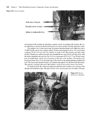
Figure 6.18 Area of Incident
used, instead of the backhoe the plumbing company owned. According to the operator, the vic-
tim asked him to operate the backhoe because he was more familiar with that particular model.
The backhoe was a farm tractor type, all-purpose backhoe/loader with rubber tires and a
75-HP (56-kW), diesel, four-cylinder engine. It had a general purpose 18-in. (457 mm) bucket
weighing 255 lb (116 kg) with foot controls to swing it left (left throttle) and right (right
throttle). Hand levers raised, lowered, and extended the two-part 430-lb (195-kg) boom with
the bucket attached at the end (see Fig. 6.19) to a maximum of 25.5 ft (7.77 m). It had outrig-
gers for stabilization, which were in position on the day of the incident. The backhoe was
positioned about 4 ft (1.22 m) from the edge of the trench on the asphalt parking lot behind the
curb. The boom with attached bucket was extended and angled over and down into the trench.
The operator, if sitting in the seat of the backhoe, could not see activity down in the trench.
To repair the leak, the victim and apprentice plumber had to remove two sections of the
old pipe and install new pipe. The pipe sections were cast iron and were 10 inches (250 mm)
Figure 6.19 Bucket
and Boom of Backhoe