Page 264 - Fair, Geyer, and Okun's Water and wastewater engineering : water supply and wastewater removal
P. 264

JWCL344_ch06_194-229.qxd  8/2/10  9:51 PM  Page 224


                    224  Chapter 6  Water Distribution Systems: Components, Design, and Operation
                        Elevation of loop ABCD is 600 m and the value of C for          B                   C
                    all pipes   100.
                        Determine the needed diameter of main SA so that the
                    residual pressure at any point in the network ABCD does not
                    drop below 250 kPa.                                          A                              D
                                                                    Q
                    6.5  Potable water is supplied to a city via an 800-mm trans-  Elevation
                    mission line at a flow rate of 550 L/s (see Fig. 6.22). A pressure    1,500 ft
                    gauge located 500 m upstream from point A registers 6.5 bars at                            Q
                    normal operation. The following data are given:                               E  Elevation
                                                                               F                       1,485 ft
                                Pipe    d (mm)   L (m)
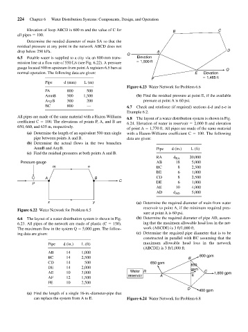
                                                                    Figure 6.23 Water Network for Problem 6.6
                                PA        800     500
                                AmnB      500    1,500                  (b) Find the residual pressure at point E, if the available
                                AxyB      300     200                      pressure at point A is 60 psi.
                                BC        800     —                 6.7  Check and reinforce (if required) sections d-d and e-e in
                                                                    Example 6.2.
                    All pipes are made of the same material with a Hazen-Williams  6.8  The layout of a water distribution system is shown in Fig.
                    coefficient C   100. The elevations of points P, A, and B are  6.24. Elevation of water in reservoir   2,000 ft and elevation
                    650, 660, and 635 m, respectively.
                                                                    of point A   1,770 ft. All pipes are made of the same material
                        (a) Determine the length of an equivalent 500-mm single  with a Hazen-Williams coefficient C   100. The following
                           pipe between points A and B.             data are given:
                        (b) Determine the actual flows in the two branches
                           AmnB and AxyB.                                        Pipe   d (in.)  L (ft)
                        (c) Find the residual pressures at both points A and B.
                                                                                 RA     d RA   20,000
                     Pressure gauge                                              AB      18     5,000
                                   m               n                             BC       8     2,500
                                                                                 BE       6     1,000
                                A                     B                          CD       8     2,500
                                                                C
                          P                                                      DE       6     1,000
                                                                                 AE      10     4,000
                                                                                 AD     d AD    5,000

                                 x                   y                  (a) Determine the required diameter of main from water
                                                                           reservoir to point A, if the minimum required pres-
                    Figure 6.22 Water Network for Problem 6.5
                                                                           sure at point A is 60 psi.
                    6.6  The layout of a water distribution system is shown in Fig.  (b) Determine the required diameter of pipe AD, assum-
                    6.23. All pipes of the network are made of plastic (C   150).  ing that the maximum allowable head loss in the net-
                    The maximum flow in the system Q   5,000 gpm. The follow-  work (ABCDE) is 3 ft/1,000 ft.
                    ing data are given:                                 (c) Determine the required pipe diameter that is to be
                                                                           constructed in parallel with BC assuming that the
                                 Pipe   d (in.)  L (ft)                    maximum allowable head loss in the network
                                                                           (ABCDE) is 3 ft/1,000 ft.
                                 AB      14     1,000
                                                                                                    800 gpm
                                 BC      14     2,500                                          B
                                 CD      14      500                          650 gpm
                                                                                                850
                                 DE      14     2,000                                           gpm
                                 AE      10     3,000                Water  R                   E     C   1,800 gpm
                                 AF      12     1,500               reservoir     A
                                 FE      10     2,500
                                                                                              D
                                                                                                   400 gpm
                        (a) Find the length of a single 16-in.-diameter-pipe that
                           can replace the system from A to E.      Figure 6.24 Water Network for Problem 6.8
   259   260   261   262   263   264   265   266   267   268   269