
Page 265 - Fair, Geyer, and Okun's Water and wastewater engineering : water supply and wastewater removal
P. 265
JWCL344_ch06_194-229.qxd 8/2/10 9:51 PM Page 225
Problems/Questions 225
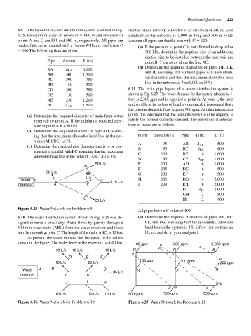
6.9 The layout of a water distribution system is shown in Fig. and the whole network is located at an elevation of 340 m. Each
6.25. Elevation of water in reservoir 600 m and elevation of quadrant in the network is 1,000 m long and 500 m wide.
points A and C are 531 and 500 m, respectively. All pipes are Assume all pipes are ductile iron with C 100.
made of the same material with a Hazen-Williams coefficient C (a) If the pressure at point C is not allowed to drop below
100.The following data are given: 300 kPa, determine the required size of an additional
ductile pipe to be installed between the reservoir and
Pipe d (mm) L (m) point B, 7 km away along the line AC.
(b) Determine the required diameters of pipes DE, CK,
RA d RA 6,000
AB 400 1,500 and JI, assuming that all three pipes will have identi-
BC 200 750 cal diameters and that the maximum allowable head
BE 150 300 loss in the network is 3 m/1,000 m (3%).
CD 300 750 6.11 The main pipe layout of a water distribution system is
DE 150 300 shown in Fig. 6.27. The water demand for the system (domestic
AE 250 1,200 fire) is 2,300 gpm and is supplied at point A. At point I, the most
AD d AD 1,500 unfavorable as far as loss of head is concerned, it is assumed that a
fire plus the domestic flow requires 900 gpm. At other intersection
(a) Determine the required diameter of main from water points it is estimated that the amounts shown will be required to
reservoir to point A, if the minimum required pres- satisfy the normal domestic demand. The elevations at intersec-
sure at point A is 450 kPa. tions of mains are as follows:
(b) Determine the required diameter of pipe AD; assum-
ing that the maximum allowable head loss in the net- Point Elevation (ft) Pipe d (in.) L (ft)
work (ABCDE) is 3%. A 95 AB 500
(c) Determine the required pipe diameter that is to be con- B 95 BC d AB 400
structed in parallel with BC assuming that the maximum C 100 BE d BC 8 1,600
allowable head loss in the network (ABCDE) is 3%.
D 95 CF d CF 1,600
50 L/s E 100 AD 16 1,600
B
F 105 DE 6 500
30 L/s
55 G 100 EF 6 500
L/s
Water R C 115 L/s H 105 DG 14 2,000
reservoir A E I 109 EH 6 2,000
FI d FI 2,000
GH 12 500
D
25 L/s HI 12 400
Figure 6.25 Water Network for Problem 6.9
All pipes have a C value of 100.
6.10 The water distribution system shown in Fig. 6.26 was de- (a) Determine the required diameters of pipes AB, BC,
signed to serve a small city. Water flows by gravity through a CF, and FG, assuming that the maximum, allowable
400-mm water main (ABC) from the water reservoir and feeds head loss in the system is 2%. (Hint: Use sections aa,
into the network at point C. The length of the main, ABC, is 10 km. bb, cc, and dd in your analysis.)
At present, the water demand has increased to the values
shown in the figure. The water level in the reservoir is at 400 m, 100 gpm b 200 gpm 2,300 gpm
c a
10 L/s 10 L/s 10 L/s G D A
d
D E F a
100 gpm 300 gpm
10 L/s 20 L/s 200 gpm
Water A B G 35 L/s H E B
reservoir C K
J I H
C b
I d F c
10 L/s 10 L/s 10 L/s 900 gpm 150 gpm 350 gpm
Figure 6.26 Water Network for Problem 6.10 Figure 6.27 Water Network for Problem 6.11