Page 268 - Fair, Geyer, and Okun's Water and wastewater engineering : water supply and wastewater removal
P. 268

JWCL344_ch06_194-229.qxd  8/19/10  4:58 PM  Page 228


                    228  Chapter 6  Water Distribution Systems: Components, Design, and Operation
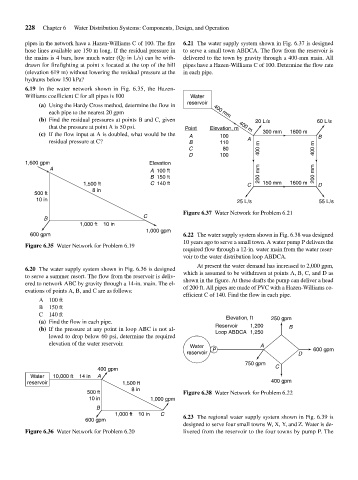
                    pipes in the network have a Hazen-Williams C of 100. The fire  6.21 The water supply system shown in Fig. 6.37 is designed
                    hose lines available are 150 m long. If the residual pressure in  to serve a small town ABDCA. The flow from the reservoir is
                    the mains is 4 bars, how much water (Q F in L/s) can be with-  delivered to the town by gravity through a 400-mm main. All
                    drawn for firefighting at point x located at the top of the hill  pipes have a Hazen-Williams C of 100. Determine the flow rate
                    (elevation 619 m) without lowering the residual pressure at the  in each pipe.
                    hydrants below 150 kPa?
                    6.19 In the water network shown in Fig. 6.35, the Hazen-
                    Williams coefficient C for all pipes is 100       Water
                                                                     reservoir
                        (a) Using the Hardy Cross method, determine the flow in
                           each pipe to the nearest 20 gpm                   400 mm
                        (b) Find the residual pressures at points B and C, given          20 L/s             60 L/s
                           that the pressure at point A is 50 psi.  Point   Elevation, m  400 m
                        (c) If the flow input at A is doubled, what would be the  A  100    300 mm  1600 m   B
                           residual pressure at C?                    B        110     A
                                                                      C         80         400 m            400 m
                                                                      D        100
                    1,600 gpm                             Elevation
                           A                              A  100 ft
                                                          B  150 ft                        200 mm           200 mm
                                      1,500 ft            C  140 ft                    C    150 mm  1600 m   D
                                        8 in
                       500 ft
                       10 in                                                        25 L/s                   55 L/s

                                                                    Figure 6.37 Water Network for Problem 6.21
                                                        C
                          B
                                     1,000 ft    10 in
                                                         1,000 gpm
                     600 gpm                                        6.22 The water supply system shown in Fig. 6.38 was designed
                                                                    10 years ago to serve a small town. A water pump P delivers the
                    Figure 6.35 Water Network for Problem 6.19
                                                                    required flow through a 12-in. water main from the water reser-
                                                                    voir to the water distribution loop ABDCA.
                                                                        At present the water demand has increased to 2,000 gpm,
                    6.20 The water supply system shown in Fig. 6.36 is designed
                    to serve a summer resort. The flow from the reservoir is deliv-  which is assumed to be withdrawn at points A, B, C, and D as
                    ered to network ABC by gravity through a 14-in. main. The el-  shown in the figure. At these drafts the pump can deliver a head
                    evations of points A, B, and C are as follows:  of 200 ft. All pipes are made of PVC with a Hazen-Williams co-
                                                                    efficient C of 140. Find the flow in each pipe.
                        A 100 ft
                        B 150 ft
                        C 140 ft                                                 Elevation, ft
                        (a) Find the flow in each pipe.                                        250 gpm
                        (b) If the pressure at any point in loop ABC is not al-  Reservoir    1,200  B
                                                                              Loop ABDCA  1,250
                           lowed to drop below 60 psi, determine the required
                           elevation of the water reservoir.
                                                                      Water                A
                                                                     reservoir  P                      D   600 gpm
                                                                                       750 gpm
                                          400 gpm                                               C
                      Water  10,000 ft    14 in  A
                    reservoir                    1,500 ft                                      400 gpm
                                                    8 in
                                       500 ft                       Figure 6.38 Water Network for Problem 6.22
                                       10 in              1,000 gpm
                                          B
                                               1,000 ft    10 in  C  6.23 The regional water supply system shown in Fig. 6.39 is
                                      600 gpm
                                                                    designed to serve four small towns W, X, Y, and Z. Water is de-
                    Figure 6.36 Water Network for Problem 6.20      livered from the reservoir to the four towns by pump P. The
   263   264   265   266   267   268   269   270   271   272   273