Page 266 - Fair, Geyer, and Okun's Water and wastewater engineering : water supply and wastewater removal
P. 266

JWCL344_ch06_194-229.qxd  8/2/10  9:51 PM  Page 226


                    226  Chapter 6  Water Distribution Systems: Components, Design, and Operation
                        (b) What is the minimum possible pressure at point I? Is  12 in.                  12 in.
                           it acceptable? Assume that a pressure of 30 psi is  8 in.  6 in.  8 in.  6 in.     12 in.
                           available at point A.                                400 ft
                    6.12 The elevations at various points in the water distribution  500 ft                  6 in.
                    system shown in Fig. 6.28 are as follows:

                                  A, B, and D  528.5 m                                                       6 in.
                                  C, E, and G  530.0 m
                                                                    2,000 ft              X
                                  F and H    531.5 m
                                                                                                             6 in.
                                  I          532.5 m
                                                                                                             6 in.
                    24 L/s              13 L/s              172 L/s
                          G                   D           A
                                                                                                              12 in.

                     8 L/s              16 L/s               26 L/s                     2,500 ft
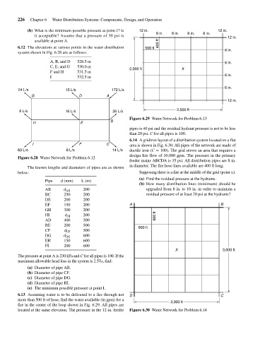
                                                                    Figure 6.29 Water Network for Problem 6.13
                                                            B
                          H                    E
                                                                    pipes is 40 psi and the residual hydrant pressure is not to be less
                                                                    than 20 psi. C for all pipes is 100.
                                                                    6.14 A gridiron layout of a distribution system located on a flat
                          I                   F           C         area is shown in Fig. 6.30. All pipes of the network are made of
                    63 L/s               8 L/s               14 L/s  ductile iron (C   100). The grid serves an area that requires a
                                                                    design fire flow of 10,000 gpm. The pressure in the primary
                    Figure 6.28 Water Network for Problem 6.12
                                                                    feeder mains ABCDA is 35 psi. All distribution pipes are 8 in.
                                                                    in diameter. The fire hose lines available are 400 ft long.
                        The known lengths and diameters of pipes are as shown
                    below:                                              Supposing there is a fire at the middle of the grid (point x):
                                                                        (a) Find the residual pressure at the hydrants.
                                Pipe  d (mm)   L (m)
                                                                        (b) How many distribution lines (minimum) should be
                                AB      d AB    200                        upgraded from 8 in. to 10 in. in order to maintain a
                                BC      250     200                        residual pressure of at least 20 psi at the hydrants?
                                DE      200     200
                                EF      150     200                 A                                      B
                                GH      300     200
                                HI      d HI    200                            600 ft
                                AD      400     500
                                BE      200     500                     600 ft
                                CF      d CF    500
                                DG      d DG    600
                                EH      150     600
                                FI      200     600
                                                                                        X                   3,000 ft
                    The pressure at point A is 230 kPa and C for all pipes is 100. If the
                    maximum allowable head loss in the system is 2.5‰, find:
                        (a) Diameter of pipe AB.
                        (b) Diameter of pipe CF.
                        (c) Diameter of pipe DG.
                        (d) Diameter of pipe HI.
                        (e) The minimum possible pressure at point I.
                    6.13 Assuming water is to be delivered to a fire through not  D                        C
                    more than 500 ft of hose, find the water available (in gpm) for a  3,000 ft
                    fire in the center of the loop shown in Fig. 6.29. All pipes are
                    located at the same elevation. The pressure in the 12-in. feeder  Figure 6.30 Water Network for Problem 6.14
   261   262   263   264   265   266   267   268   269   270   271