Page 267 - Fair, Geyer, and Okun's Water and wastewater engineering : water supply and wastewater removal
P. 267

JWCL344_ch06_194-229.qxd  8/2/10  9:51 PM  Page 227


                                                                                              Problems/Questions  227
                    6.15 The layout of a loop for a city water distribution system  (a) Determine the residual pressure at the hydrants (eleva-
                    located on a flat area is shown in Fig. 6.31. All pipes of the net-  tion   645 m) if there is a fire at the center of the loop.
                    work have a Hazen-Williams C of 100. The fire hose lines avail-  (b) What sizes should lines 2 and 5 be replaced with if the
                    able are 15 0m long. If the residual pressure in the 300-mm  minimum required pressure at the hydrants is 150 kPa?
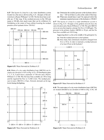
                    mains is 300 kPa, how much water (Q F ) can be withdrawn for  6.17 The layout of a loop in a water distribution system is
                    firefighting at the center of loop without lowering the residual  shown in Fig. 6.33. All pipes of the gridiron network have the
                    pressure at the hydrants below 150 kPa?         same elevation and a Hazen-Williams C of 100. The grid ABCDA
                                                                    serves an area that requires a design fire flow of 9,000 gpm. The
                       300 mm                       300 mm
                              150 mm 200 mm  150 mm                 pressure in the primary feeders ABCDA is 30 psi, and the fire
                                                         300 mm     hose lines available are 410 ft long.
                                   200 m                                Supposing there is a fire at the middle of the grid (point X);

                                                       200 mm           (a) Find the residual pressure at the hydrants.
                            200 m                                       (b) How many lines (minimum) should be changed from
                                                                           8 in. to 10 in. in order to maintain a residual pressure
                                                                           of at least 20 psi at the hydrants?
                    800 m               X              150 mm
                                                                                  2,400 ft
                                                                    A                               B
                                                       200 mm

                                                                                8 in      8 in
                                                         300 mm                              8 in
                                      800 m
                                                                                    X                2,400 ft
                    Figure 6.31 Water Network for Problem 6.15
                                                                         800 ft              8 in
                    6.16 Mains of a city water distribution loop (ABCDA) are lo-
                    cated at an elevation of 635 m (Fig. 6.32). All distribution pipes
                    1, 2, 3, 4, 5 and 6 have a diameter of 150 mm and a Hazen-   800 ft
                    Williams C of 100. The fire hose lines available are 150 m long
                    and the required fire flow is 12,200 L/min. The residual pres-
                    sure in mains ABCDA is 4 bars. Domestic demand can be neg-  D                   C
                    lected during firefighting.                     Figure 6.33 Water Network for Problem 6.17

                    A         1       2       3        B            6.18 The main pipes of a city water distribution loop (ABCDA)
                                                                    are located downhill at an elevation of 600 m (Fig. 6.34). All

                                                         225 m           A       150 mm   200 mm       B
                    4
                                                                                      250 m
                                                         225 m
                                       X                                                               150 mm
                    5                                                        250 m
                                                                    750 m               X
                                                         225 m
                    6                                                                                  200 mm

                                                         225 m


                    D                                  C                 D                             C
                        225 m   225 m   225 m   225 m                                 750 m

                    Figure 6.32 Water Network for Problem 6.16      Figure 6.34 Water Network for Problem 6.18
   262   263   264   265   266   267   268   269   270   271   272