
Page 281 - Fair, Geyer, and Okun's Water and wastewater engineering : water supply and wastewater removal
P. 281
JWCL344_ch07_230-264.qxd 8/2/10 8:44 PM Page 241
7.7 Automated Optimization 241
The following examples give step-by-step instructions on how to solve problems and
design water systems using WaterGEMS.
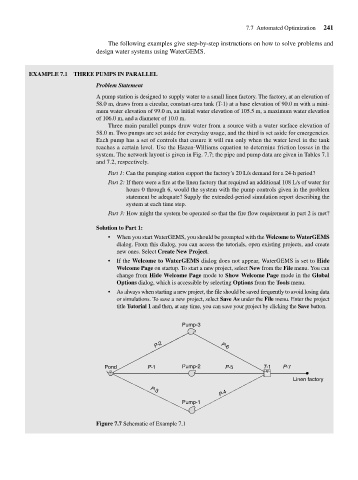
EXAMPLE 7.1 THREE PUMPS IN PARALLEL
Problem Statement
A pump station is designed to supply water to a small linen factory. The factory, at an elevation of
58.0 m, draws from a circular, constant-area tank (T-1) at a base elevation of 90.0 m with a mini-
mum water elevation of 99.0 m, an initial water elevation of 105.5 m, a maximum water elevation
of 106.0 m, and a diameter of 10.0 m.
Three main parallel pumps draw water from a source with a water surface elevation of
58.0 m. Two pumps are set aside for everyday usage, and the third is set aside for emergencies.
Each pump has a set of controls that ensure it will run only when the water level in the tank
reaches a certain level. Use the Hazen-Williams equation to determine friction losses in the
system. The network layout is given in Fig. 7.7; the pipe and pump data are given in Tables 7.1
and 7.2, respectively.
Part 1: Can the pumping station support the factory’s 20 L/s demand for a 24-h period?
Part 2: If there were a fire at the linen factory that required an additional 108 L/s of water for
hours 0 through 6, would the system with the pump controls given in the problem
statement be adequate? Supply the extended-period simulation report describing the
system at each time step.
Part 3: How might the system be operated so that the fire flow requirement in part 2 is met?
Solution to Part 1:
• When you start WaterGEMS, you should be prompted with the Welcome to WaterGEMS
dialog. From this dialog, you can access the tutorials, open existing projects, and create
new ones. Select Create New Project.
• If the Welcome to WaterGEMS dialog does not appear, WaterGEMS is set to Hide
Welcome Page on startup. To start a new project, select New from the File menu. You can
change from Hide Welcome Page mode to Show Welcome Page mode in the Global
Options dialog, which is accessible by selecting Options from the Tools menu.
• As always when starting a new project, the file should be saved frequently to avoid losing data
or simulations. To save a new project, select Save As under the File menu. Enter the project
title Tutorial 1 and then, at any time, you can save your project by clicking the Save button.
Pump-3
P-2 P-6
Pond P-1 Pump-2 P-5 T-1 P-7
Linen factory
P-4
P-3
Pump-1
Figure 7.7 Schematic of Example 7.1